Trailering Description and Operation
Table 1: North America 7–Way Trailer Connector Table 2: Export 13–Way Trailer Connector Trailering System Overview Begin the trailering system diagnosis with Diagnostic System Check - Trailering. The Diagnostic System Check - Trailering will provide a complete strategy to locate and repair a vehicle trailering electrical fault. Not following this strategy may cause additional diagnostic time and/or misdiagnosis. The trailering system consists of the following: Trailer Lighting, refer to Trailer Lamps Malfunction for additional diagnostic information. Trailer Brakes, refer to Trailer Brake Malfunction for additional diagnostic information. Trailer Battery Charging System, refer to Trailer Battery Charging Malfunction for additional diagnostic information. Trailer Detection, refer to Trailer Detection Malfunction for additional diagnostic information. Trailer Tire Pressure Monitoring System, refer to Trailer Tire Pressure Monitoring Malfunction for additional diagnostic information. Trailer Theft Detection. When a trailer is detected on a vehicle equipped with side blind zone detection, rear park assist, and/or rear cross traffic alert, the vehicle will automatically turn these features off. These features are turned off to prevent false detections due to the trailer obstructing the view of the sensors. 7–Terminal Tow Vehicle Electrical Receptacle Pinout (North America) Terminal A – Trailer Backup Lamp Control Terminal B – Ground Terminal C – Trailer Brake Control Terminal D – Right Trailer Stop/Turn Signal Lamp Control Terminal E – B+ Terminal F – Trailer Park Lamp Control Terminal G – Left Trailer Stop/Turn Signal Lamp Control 13–Terminal Tow Vehicle Electrical Receptacle Pinout (Export) Terminal 1 – Left Trailer Turn Signal Lamp Control Terminal 2 – Trailer Fog Lamp Control Terminal 3 – Ground Terminal 4 – Right Trailer Turn Signal Lamp Control Terminal 5 – Right Trailer Park Lamps Control Terminal 6 – Trailer Stop Lamps Control Terminal 7 – Left Trailer Park Lamps Control Terminal 8 – Trailer Backup Lamp Control Terminal 9 – B+ Terminal 10 – Ignition Voltage Terminal 11 – Ground Terminal 12 – Trailer Connected Signal Terminal 13 – Ground Connecting Aftermarket Accessories Some aftermarket accessories that connect to the X88 Tow Vehicle Electrical Receptacle will be recognized by the vehicle as a trailer connected, even if the accessory is not a trailer. As a result, side blind zone detection, rear park assist, and/or rear cross traffic alert will be turned off anytime the vehicle detects a trailer/accessory is connected. Vehicles equipped with U1D/UET have trailer theft detection that constantly monitors trailer connected status when enabled. This is done by randomly pulsing the lighting circuits of the trailer when the vehicle is parked. As a result, some aftermarket accessories may be turned ON/OFF when connected to the vehicle with theft detection enabled. Vehicles equipped with U1D/UET use pulse width modulation voltage (PWM) for trailer lighting functions. Some aftermarket accessories are incompatible with PWM and may not function correctly when connected to the trailer lighting circuits of the vehicle. Trailer Battery Charging System Trailer battery charging is accomplished through constant battery voltage from the X50A Engine Wiring Harness Junction Block to the X88 Tow Vehicle Electrical Receptacle. Battery voltage is supplied to terminal E at the X88 Tow Vehicle Electrical Receptacle at all times. If equipped, the trailer battery will constantly be charged by the vehicle’s electrical system anytime the trailer is connected. Some trailers require the B+ circuit to the X88 Tow Vehicle Electrical Receptacle for the trailer brakes to function. Trailer Lighting and Detection With U1D/UET
| Trailering Message | Description | ||
|---|---|---|---|
| Check Trailer Left Turn Signal Lamp | The K68 Trailer Lighting Control Module detects a fault on the left trailer stop/turn lamp control circuit | ||
| Check Trailer Right Turn Signal Lamp | The K68 Trailer Lighting Control Module detects a fault on the right trailer stop/turn lamp control circuit | ||
| Check Trailer Rear Lamp | The K68 Trailer Lighting Control Module detects a fault on the trailer park lamp control circuit. | ||
| Check Trailer Reversing Lamp | The K68 Trailer Lighting Control Module detects a fault on the trailer backup lamp control circuit. | ||
| Check Trailer Brake Lamps | The K68 Trailer Lighting Control Module detects a fault on the left and/or right trailer stop/turn lamp control circuits | ||
| {JL1} Check Trailer Wiring | The K67 Trailer Brake Power Control Module detects a fault on the trailer brake control circuit or the trailer was disconnected. |
| Trailering Message | Description |
|---|---|
| Lane Change Alert Off | Reminder to the user that lane change alerts are turned off anytime a trailer is detected. |
| Rear Cross Traffic Alert Off | Reminder to the user that rear cross traffic alerts are turned off anytime a trailer is detected. |
| Rear Park Assist Off | Reminder to the user that rear park assist is turned off anytime a trailer is detected. |
| Remember to turn On Tow/Haul Mode | Reminder to the user to turn ON Tow/Haul Mode when towing. |
| {JL1} Service Trailer Brake System | The K67 Trailer Brake Power Control Module detects a fault on the trailer brake control circuit. |
| Service Trailer Tire Monitor System | The K214 Trailer Tire Pressure Indicator Module detects one or more issues with the trailer tire pressure monitoring system. |
| Trailer Detected | The K68 Trailer Lighting Control Module detects a trailer has been connected to the X88 Trailer Connector. |
| {JL1} Trailer Brakes Detected | The K67 Trailer Brake Power Control Module detects a trailer with trailer brakes has been connected to the X88 Trailer Connector. |
| Trailer Disconnected Check Connection | The K68 Trailer Lighting Control Module detects a trailer has been disconnected from the X88 Trailer Connector. |
| Trailer Tire Pressure High | The K214 Trailer Tire Pressure Indicator Module detects one or more of the trailer tire pressures is high. |
| Trailer Tire Pressure Low | The K214 Trailer Tire Pressure Indicator Module detects one or more of the trailer tire pressures is low. |
| Trailer Tire Sensor Fault | The K214 Trailer Tire Pressure Indicator Module detects one or more of the trailer tire pressure sensors has a fault. |
| Trailer Tire Temperature High | The K214 Trailer Tire Pressure Indicator Module detects one or more of the trailer tire temperatures is too high. |
Export 13–Way Trailer Connector Trailer Messages The driver information center (P16 Instrument Cluster) or infotainment screen (P17 Info Display Module) may display one or more of the following messages to the user related to trailering. Export 13–Way Trailer Connector
| Trailering Message | Description |
|---|---|
| Check Trailer Left Turn Signal Lamp | The K68 Trailer Lighting Control Module detects a fault on the left trailer turn lamp control circuit |
| Check Trailer Right Turn Signal Lamp | The K68 Trailer Lighting Control Module detects a fault on the right trailer turn lamp control circuit |
| Check Trailer Rear Lamp | The K68 Trailer Lighting Control Module detects a fault on one or both of the trailer park lamp control circuit(s). |
| Check Trailer Reversing Lamp | The K68 Trailer Lighting Control Module detects a fault on the trailer backup lamp control circuit. |
| Check Trailer Brake Lamps | The K68 Trailer Lighting Control Module detects a fault on the trailer stop lamp control circuit. |
| Check Trailer Rear Fog Lamp | The K68 Trailer Lighting Control Module detects a fault on the trailer fog lamp control circuit. |
| Lane Change Alert Off | Reminder to the user that lane change alerts are turned off anytime a trailer is detected. |
| Rear Cross Traffic Alert Off | Reminder to the user that rear cross traffic alerts are turned off anytime a trailer is detected. |
| Rear Park Assist Off | Reminder to the user that rear park assist is turned off anytime a trailer is detected. |
Trailer Theft Detection (With U1D/UET Only) Trailer theft monitoring can be turned ON and OFF through the vehicle Trailer App. When enabled, any time the trailer theft deterrent system is armed, the trailer lighting circuits are constantly monitored to determine if a trailer is connected for trailer theft deterrent purposes. With the key OFF, the K68 Trailer Lamp Control Module will randomly pulse the lighting circuits of the trailer to verify it is still connected by monitoring the voltage drop of the circuit. Depending on the configuration of the trailer lights, the trailer lights may randomly flash as part of the trailer theft deterrent function. These flashes correspond to when the K68 Trailer Lamp Control Module pulses the lighting circuits to ensure the trailer is still connected and is considered normal. If the trailer is disconnected while the trailer theft deterrent system is armed, the vehicle will flash the exterior lights and cycle the horn to alert of a trailer theft event. Refer to Theft Systems Description and Operation for more information on the content theft deterrent system. Trailer Brakes (JL1) The vehicle is equipped with the following trailer braking components: K160 Brake System Control Module K67 Trailer Brake Control Module S76 Trailer Brake Control Switch Trailer Brake Driver Information Center Display Trailer Brake Circuits Circuit 2223 is the trailer brake apply signal circuit. The K160 Brake System Control Module receives vehicle braking force data and/or data from the application of the manual trailer brake slide lever. The brake system control module responds by applying the appropriate amount of pulse width modulated (PWM) voltage based on the amount of trailer brake application desired. The K67 Trailer Brake Power Control Module responds to the signal circuit by applying the appropriate amount of PWM voltage to the trailer auxiliary control circuit 47. Circuit 2224 is the trailer brake enable signal circuit. The K160 Brake System Control Module applies voltage to the enable circuit anytime a LIN data communication fault is not present, a trailer is connected, and the vehicle brakes are being applied. The enable circuit must have voltage applied to it before the K133 Trailer Brake Power Control Module applies the appropriate amount of pulse width modulated (PWM) voltage to the trailer auxiliary control circuit 47. Circuit 2733 is the brake system control module LIN bus 2 circuit. The K160 Brake System Control Module, K67 Trailer Brake Power Control Module, and the S76 Trailer Brake Control Switch all communicate through the brake system control module LIN bus 2 circuit. If the LIN bus has a fault on the circuit, trailer braking will be disabled until the fault is repaired. Circuit 47 is the trailer auxiliary control circuit. The K133 Trailer Brake Power Control Module responds to signal circuit 2223 and enable circuit 2224 by applying the appropriate amount of PWM voltage to the trailer auxiliary control circuit. A properly functioning trailer will apply the appropriate amount of braking force to the brakes of the trailer. The Trailer Brake Control System is compatible with two types of Trailer Brake Systems as listed below:
- Electric Brakes A controlled electrical output signal energizes an electric-magnet/lever arm assembly that directly actuates the brake mechanism. The GDS name for this system is “Electromagnetic Brakes”.
- Electric Over Hydraulic Brakes A controlled electrical output signal energizes a remote, trailer mounted hydraulic pump to build brake pressure in a closed hydraulic system on the trailer. The hydraulic fluid pressure actuates the brake mechanism. The GDS name for this system is “Electrohydraulic Brakes”. Trailer Brake Output Versus Trailer Brake Type The trailer brake system characterizes the trailer brakes as either Electric Brake or Electric Over Hydraulic Brake automatically. This characterization may be affected by the number, type, and age of the trailer brake magnets, as well as any other devices installed on the trailer brakes (i.e. adapters for Electric Over Hydraulic brake functionality). The trailer brake system is fully operational with either characterization. Sliding the manual trailer brake apply lever will produce output at zero speed for either characterization. The user gain allows the driver to adjust the amount of trailer brake output to match the trailer load and road surface. The controller determines the desired trailer brake output and provides a control signal to the K67 Trailer Brake Control Module (TBPM). The K67 Trailer Brake Control Module amplifies the signal and provides the output required to activate the Electric or Electric Over Hydraulic trailer brakes. The trailer brake control can support up to a maximum of four axles with electric trailer brakes (8 brake magnets). Connecting a trailer that is not compatible with the trailer brake system may result in reduced or complete loss of trailer braking. There may be an increase in stopping distance or trailer instability which could result in personal injury or damage to the vehicle, trailer or other property. An aftermarket controller may be available for use with incompatible trailer brake systems. To determine the type of brakes on your trailer and the availability of controllers, check with your trailer manufacturer or dealer. Do not power up an aftermarket controller with the factory brake controller at the same time. Trailer Brake Control Panel The S76 Trailer Brake Control Switch contains the trailer gain and manual apply switches. It is located in the vehicle center stack. Refer to the owner’s manual for more information on the location. The control panel and switches allows you to adjust the amount of output, referred to as trailer gain, available to the Electric or Electric Over Hydraulic brakes. It also allows you to manually apply the trailer brakes. The trailer brake control switch is used along with the trailer brake display page on the driver information center to adjust and display power output to the trailer brakes. Manual Trailer Brake Apply The manual trailer brake apply lever is located on the S76 Trailer Brake Control Switch and is used to apply the trailer’s Electric or Electric Over Hydraulic brakes independent of the vehicle’s brakes. This lever is used in the trailer gain adjustment procedure to properly adjust the power output to the trailer brakes. Sliding the lever will apply only the trailer brakes. The power output to the trailer is indicated in the trailer brake display page in the Driver Information Center (DIC). If the vehicle’s service brakes are applied while using the manual trailer brake apply lever, the trailer brake control output power will be the greater of the two. The trailer and the vehicle’s brake lamps will come on when either the vehicle’s braking or manual trailer brakes are applied. Trailer Brake Gain Adjustment Trailer gain should be set for a specific trailering condition and must be adjusted any time vehicle loading, trailer loading or road surface conditions change. It is important to re-adjust trailer gain any time the tow vehicle, trailer loading or road surface conditions change or if you notice trailer wheel lock-up at any time while you are towing. Setting the trailer gain properly is needed for the best trailer stopping performance. A trailer that is over-gained may result in locked trailer brakes. A trailer that is under-gained may result in not enough trailer braking. Both of these conditions may result in poor stopping and stability of the vehicle and trailer. Trailer Gain Adjustment Procedure Adjust trailer gain in 0.5 step increments up to 10 gain setting by using the gain adjustment +/− buttons on the trailer brake control panel switch. Pressing and holding a gain button will cause the trailer gain to continuously increment or decrement. To turn the output to the trailer off, set the gain to zero. Drive the tow vehicle and trailer combination on a level surface representative of the towing condition and free of traffic at approximately 32–40 km/h (20–25 mph) and fully apply the manual trailer brake apply lever mechanism located on the trailer brake control panel switch. Adjusting the trailer gain at slower speeds may result in an incorrect gain setting. Adjust the trailer gain to just below the threshold of trailer wheel lock-up . Trailer wheel lock-up may not occur if towing a heavily loaded trailer. In this case, adjust the trailer gain to the highest allowable setting for the towing condition. Trailer Brake Gain and Output Display This display menu can be accessed by scrolling through the DIC menu, or any time the trailer gain +/− button is depressed, or the manual trailer brake apply lever is actuated. The trailer output is displayed from 0 to full output and indicates the output power provided to the trailer brakes, relative to the gain setting. After the electrical connection is made to a trailer equipped with electric brakes or electric over hydraulic brakes, the TRAILER CONNECTED message will be displayed momentarily on the DIC. The Trailer Brake Display Page can be selected on the DIC showing TRAILER GAIN and OUTPUT, after all vehicle related service messages are acknowledged by the driver. Depending on which instrument panel cluster is in the vehicle, the DIC may display dashed lines, a greyed out display, or it may be blank signifying a disconnected trailer or a trailer brake fault condition. Trailer Brake Driver Information Center Indicators and Messages Trailer Brake Detection The K67 Trailer Brake Control Module constantly monitors the trailer auxiliary control circuit from Terminal C at the X88 Trailer connector. When a trailer is connected with trailer brakes, the K67 Trailer Brake Control Module senses the connection and alerts the driver with a Trailer Connected message. If the K67 Trailer Brake Control Module senses a fault, or the trailer becomes disconnected, the vehicle will alert the driver with a Check Trailer Wiring message. The following indicators are used to inform the driver of several different conditions: Trailer Connected This message will be briefly displayed when a trailer with Electric or Electric Over Hydraulic brakes is first connected to the vehicle. This message will automatically turn off in about ten seconds. The driver can also acknowledge this message before it automatically turns off. Check Trailer Wiring This message will be displayed if: The system detects that a trailer with Electric or Electric Over Hydraulic brakes is connected to the vehicle and then the trailer harness becomes disconnected from the vehicle. The trailer connection is recognized initially and then a disconnect occurs while the vehicle is stationary. This message will automatically turn off in about thirty seconds. This message will also turn off if the driver selects to turn this message off or if the trailer harness is reconnected. A disconnect of the trailer wiring harness occurs while the vehicle is moving. The Check Trailer Wiring message will continue until the ignition is turned off. The message will also turn off if the driver selects to turn this message off or it the trailer harness is re-connected. There is an electrical fault in the wiring to the electric trailer brakes. The Check Trailer Wiring message will continue as long as there is an electrical fault in the trailer wiring. This message will also turn off if the driver acknowledges this message off. A poor connection at the 7–way connector may cause the Check Trailer Wiring message. Some aftermarket 7–way trailer side connector adapters or plugs may cause deformation or excessive wear to the vehicle’s trailer terminals. It is recommended that you use an OEM or Pollak heavy duty 7–way trailer side connector adapter. Service Trailer Brake System This message will be displayed when there is a problem with the trailer brake control system. The trailer brake system may not be fully functional, or may not be functioning at all. The trailer brake system is designed to provide trailer braking, if possible, even when faults prevent it from being fully functional. This reduced functionality includes:
- Providing trailer braking when the master cylinder pressure or brake pedal switch are faulted.
- Providing trailer braking when hill start assist and trailer sway control communication is faulted.
- Providing trailer braking when certain manual trailer brake apply lever faults are present. Trailer Tire Pressure Monitoring Special Tools EL-46079/J-46079 Tire Pressure Monitor Diagnostic Tool EL-50448 Tire Pressure Monitor Sensor Activation Tool EL-52641 Trailer Presence Simulator Tool For equivalent regional tools, refer to Special Tools. The Trailer Tire Pressure Monitor System is designed to monitor the pressure of the trailer tires, and warn the driver when a low pressure condition exists. Four Trailer Tire Pressure Monitor System sensors may be provided in the vehicle’s glove box as an accessory when equipped. The system can accommodate a trailer with up to (6) tires if additional sensors are purchased from the dealership. Also, the system can be paired with up to (5) individual trailers. The sensors must be mounted onto each tire and wheel assembly, and the sensors must be learned by the vehicle by following the learning procedure as shown in the Trailering App section of this manual. For sensor installation assistance, please contact your trailer service center or tire service center. The Trailer Tire Pressure Monitor System sensors monitor the air pressure in the trailer tires and transmit the trailer tire pressure readings to a receiver located in the vehicle. The trailer tire pressure sensors can transmit up to 23 feet (7 meters) from the hitch receiver of the vehicle. The tire pressure values can be viewed in the trailering app in the vehicle’s center stack. Trailering Diagnostic Tools In some situations when diagnosing trailer tire pressure monitoring, trailer lighting, or integrated trailer brakes, it may be necessary to connect the vehicle to a trailer to confirm proper operation. Performing this activity may prove difficult in the service environment since trailers are not often available for diagnostic use, may have existing electrical issues outside of the issues a technician is attempting to diagnose, or simply may be too unwieldily to connect for diagnosis. With all this in mind, it may be helpful to build or create a tool that can be plugged into the vehicle’s trailer connector and simulate a connected trailer. This tool would include park lamps, stop lamps, and a reverse lamp for lighting and trailer tire pressure monitoring diagnosis. It can be expanded to include trailer brake magnets to diagnose integrated trailer brake concerns. Also, an additional lamp can be included to diagnose the B+ circuit to the trailer. Trailer issues are NOT covered under warranty, but these tools may be used to verify the vehicle is functioning properly and to help the customer understand and correct any trailer related issues if they so choose. Available Trailer Presence Simulator Tool
| Illustration | Tool Number/Description |
|---|---|
| EL-52641 Trailer Presence Simulator Tool |
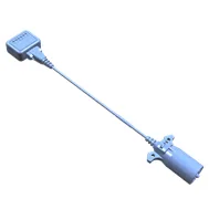
Simulated Trailer Lighting Creating a tool to simulate a connected trailer can be used to diagnose issues with trailer lighting, trailer brake (if equipped), the Trailering App (if equipped), and trailer tire pressure monitoring system (if equipped). If the vehicle is equipped with a K68 Trailer Lamp Control Module (U1D/UET), the module monitors the current on the lighting circuits to determine a trailer has been connected. The Trailer Lamp Control Module pulses current on the trailer lighting circuits every 42 minutes to monitor for a connected trailer. If a current draw greater than 55mA is detected, the Trailer Lamp Control Module recognizes this as a connected trailer. This will enable any trailer lighting controlled by the Trailer Lamp Control Module. The Center Stack Module will also use this trailer detection as a cue to enable the Trailering App and trailer tire pressure monitoring functions. Creating a Simulated Trailer Lighting Tool Parts needed: 7-way RV trailer connector Qty: 1
- Connect a 12 gauge wire to the ground terminal of the 7-way trailer connector and the ground circuit of each combination trailer park/stop/turn lamp and the reverse lamp in parallel.
- Connect an 18 gauge wire between the park lamp terminal of the 7-way trailer connector and the park lamp circuit of each combination trailer park/stop/turn lamp in parallel.
- Connect an 18 gauge wire between the left turn/stop lamp terminal of the 7-way trailer connector and the turn/stop lamp circuit of left trailer park/stop/turn lamp.
- Connect an 18 gauge wire between the right turn/stop lamp terminal of the 7-way trailer connector and the turn/stop lamp circuit of right trailer park/stop/turn lamp.
- Connect an 18 gauge wire between the reverse lamp terminal of the 7-way trailer connector and the reverse lamp.
- Mount the left combination trailer park/stop/turn lamp, right combination trailer park/stop/turn lamp, and reverse lamp to the mounting board.
- Plug the 7-way RV trailer connector to the vehicle and verify functionality. Simulated Trailer Brakes Creating a tool to simulate trailer brakes can be used to diagnose trailer brake issues. The trailer brake control system is compatible with two types of trailer brake systems: electromagnetic or electro-over hydraulic trailer brakes. The Brake System Control Module must determine which type of brakes the trailer is equipped with so the system can output correctly for the trailer’s brake system. Because the Brake System Control Module has to determine the type of trailer brake system that is being used, it can be sensitive to a variety of trailer wiring issues. The Trailer Brake Control Module continuously sends a test pulse out on the trailer brake control circuit (circuit 47) to determine if a trailer with trailer brakes has been connected. How the pulse reacts when a trailer is connected is how the Trailer Brake Control Module determines which type of braking system the trailer is equipped with. Even after the system detects the trailer, Trailer Brake Control Module will continue to send this test pulse on the trailer brake control circuit, which now is monitoring both the truck and trailer circuitry. The trailer brake control circuit continues to be monitored for any faults so the driver can be notified of any issues that may occur within the truck or trailer, as well as, to determine when the trailer is disconnected from the truck. Creating a Simulated Trailer Brake Tool Parts needed: 7-way RV trailer connector Qty: 1 Electric trailer brake magnets Qty: 2, 4, 6, or 8 Reverse lamp Qty: 1 Mounting board Qty: 1 12 gauge wire and terminals/connectors Qty: As needed
- Connect a 12 gauge wire to the ground terminal of the 7-way trailer connector.
- Connect a 12 gauge wire to the brake controller output terminal of the 7-way trailer connector.
- Connect the trailer brake magnets to the 12 gauge wires from the 7-way trailer connector in parallel.
- Mount the trailer brake magnets to the mounting board.
- Plug the 7-way RV trailer connector to the vehicle and verify functionality.