Front Shock Absorber and Spring Removal and Installation - Right Side (F47)
Front Shock Absorber and Spring Removal and Installation - Right Side (F47)
- Raise the vehicle until the tires are off the ground. Lifting and Jacking the Vehicle
- Using the scan tool, deflate the air spring that will be serviced.
- Remove the front tire and wheel assembly. Tire and Wheel Removal and Installation
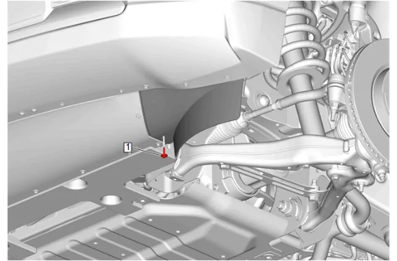
- { If equipped } Front Tire Front Air Deflector Bolt - Right Side (1) » Remove
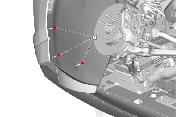
- Front Wheelhouse Liner Bolt - Right Side (1) » Remove [3x]
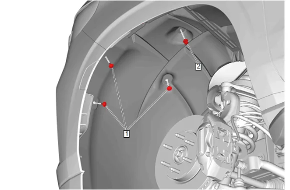
- Front Wheelhouse Liner Bolt - Right Side (1) » Remove [3x]
- Front Wheelhouse Liner Retainer - Right Side (2) » Remove
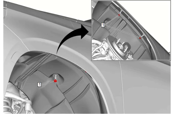
- Front Wheelhouse Liner Bolt - Right Side (1) » Remove [3x]
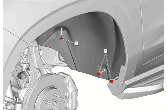
- Front Wheelhouse Liner Bolt - Right Side (1) » Remove [3x]
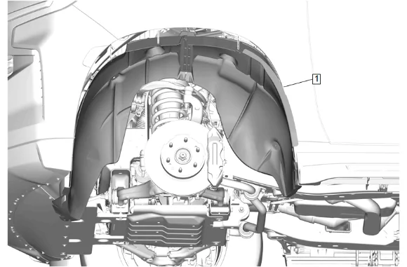
- Front Wheelhouse Liner - Right Side (1) » Remove
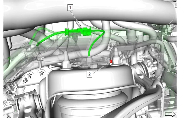
- Disconnect the right front shock absorber electrical connector (1).
- Disconnect the right air line nut (2).
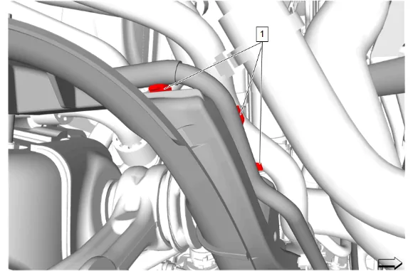
- Release the 3 air line retainers (1) from the chassis wiring harness front bracket.
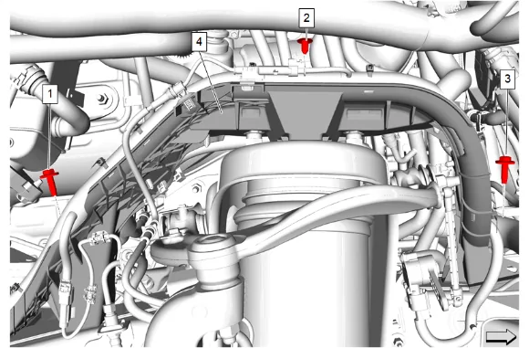
- Remove the chassis wiring harness front bracket rear bolt (1).
- Remove the chassis wiring harness front bracket retainer (2).
- Remove the chassis wiring harness front bracket front bolt (3).
- Unclip and reposition the chassis wiring harness front bracket (4) and wiring harnesses away from the shock tower.
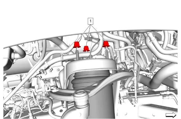
- Front Shock Absorber Nut (1) » Remove [3x]
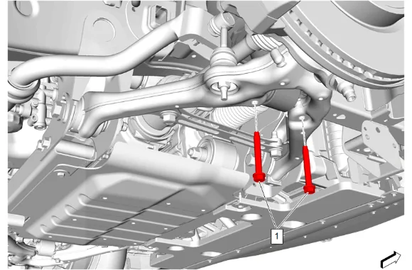
- Front Shock Absorber Bolt (1) » Remove [2x]
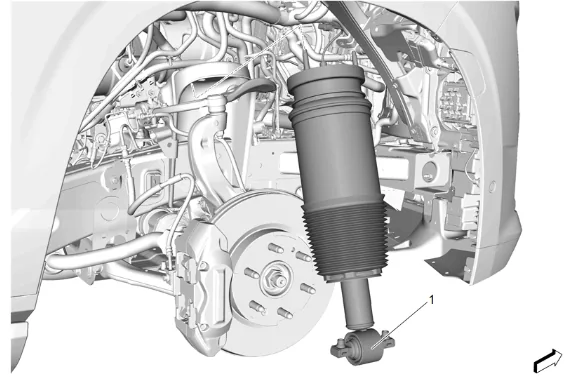
- Front Shock Absorber (1) » Remove Installation Procedure
- Apply anti-corrosion wax to the frame shock tower. Anti-Corrosion Treatment and Repair
- Support the front shock absorber using a suitable jack stand.
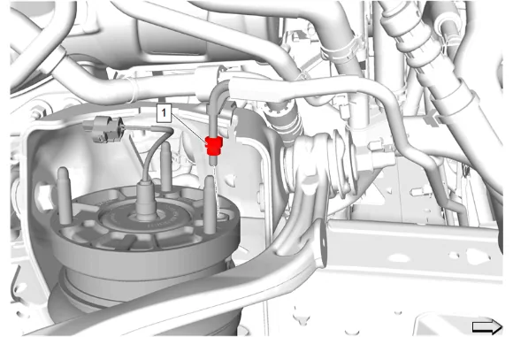
-
Reposition the air line, then install and tighten the air line nut (1). Fastener Specifications
-
Front Shock Absorber (1) » Install
-
Front Shock Absorber Nut (1) » Install and tighten [3x] — Fastener Specifications
-
Remove the front shock absorber support.
-
Front Shock Absorber Bolt (1) » Install and tighten [2x] — Fastener Specifications
-
Reposition and install the chassis wiring harness front bracket (4) and wiring harnesses to the shock tower.
-
Install and tighten the chassis wiring harness front bracket front bolt (3). Fastener Specifications
-
Install the chassis wiring harness front bracket retainer (2).
-
Install and tighten the chassis wiring harness front bracket rear bolt (1). Fastener Specifications
-
Install the 3 air line retainers (1) to the chassis wiring harness front bracket.
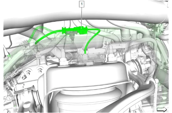
- Connect the right front shock absorber electrical connector (1).
- Front Wheelhouse Liner - Right Side (1) » Install
- Front Wheelhouse Liner Bolt - Right Side (1) » Install and tighten [3x] — Fastener Specifications
- Front Wheelhouse Liner Bolt - Right Side (1) » Install and tighten [3x] — Fastener Specifications
- Front Wheelhouse Liner Retainer - Right Side (2) » Install
- Front Wheelhouse Liner Bolt - Right Side (1) » Install and tighten [3x] — Fastener Specifications
- Front Wheelhouse Liner Bolt - Right Side (1) » Install and tighten [3x] — Fastener Specifications
- { If equipped } Front Tire Front Air Deflector Bolt - Right Side (1) » Install and tighten — Fastener Specifications
- Install the tire and wheel assembly. Tire and Wheel Removal and Installation
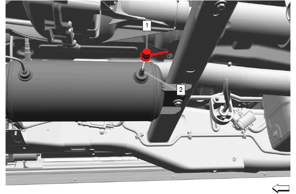
- Remove the automatic level control air supply reservoir air valve cap (1).
- Install CH-52667 Air Spring Inflator to the automatic level control air supply reservoir air valve (2) and set the regulator on the nitrogen tank to 16 Bar (232 PSI).
- Using CH-52667 Air Spring Inflator, open the valve on the pressure gage to fill the automatic level control air supply reservoir.
- Using CH-52667 Air Spring Inflator and the shop nitrogen tank, fill the automatic level control air supply reservoir to 16 Bar (232 PSI).
- Close the pressure gauge valve and remove CH-52667 Air Spring Inflator from the automatic level control air supply reservoir.
- Install the automatic level control air supply reservoir air valve cap (1) and tighten. Fastener Specifications.
- Partially lower the vehicle, but DO NOT let the wheels touch the ground.
- Using GDS2 tool, use short-term inflate to increase pressure to the air springs: Front: 6 Bar (87 PSI) Rear: 5 Bar (73 PSI)
- Using GDS2, verify automatic level control air supply tank pressure is at 16 Bar (232 PSI), if not repeat steps 22 - 27.
- Remove the support and lower the vehicle.
- With the vehicle off the hoist and on flat level ground, use the scan tool to reset trim heights. Trim Height Inspection