Camshaft Position Sensor Wire Replacement
Engine Controls and Fuel - 5.3L L84 or 6.2L L87 | Repair Instructions | Document ID: 5590111 Single Use Fastener / Component Accessory Drive Auxiliary Belt Accessory Drive Primary Belt Engine Oil Cooler Retainer [2x] Water Pump Gasket [2x] Special Tools EN-51767-2 Universal Stretchy Belt Installer Equivalent regional tools: Special Tools Removal Procedure
- Drain the cooling system. Cooling System Draining and Filling
- Disconnect the battery negative cable. Battery Negative Cable Disconnection and Connection
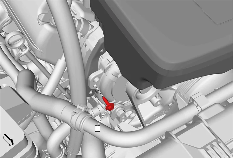
- Air Cleaner Outlet Duct Bracket Bolt (1) » Remove
- Remove the engine wiring harness from the air cleaner outlet duct bracket.
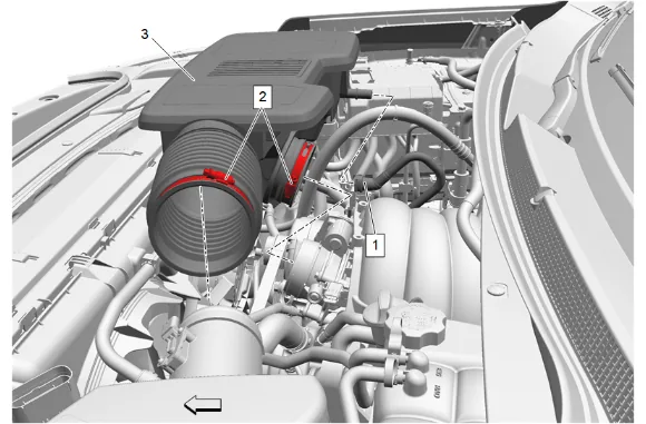
- Positive Crankcase Ventilation Fresh Air Tube (1) » Disconnect — Plastic Collar Quick Connect Fitting Service
- Air Cleaner Outlet Duct Clamp (2) » Loosen [2x]
- Air Cleaner Outlet Duct (3) » Remove
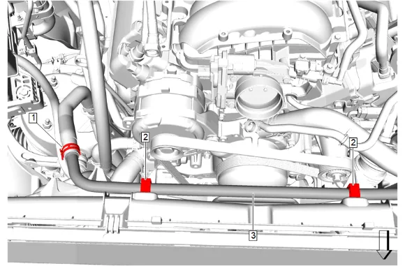
- Radiator Surge Tank Outlet Hose Clip (2) » Remove [2x]
- Radiator Surge Tank Outlet Hose (3) » Position aside
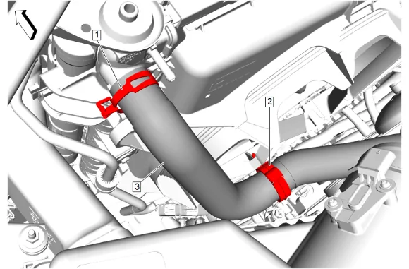
- Radiator Inlet Hose Clip (2) » Remove
- Radiator Inlet Hose Clamp (1) » Disengage — Hose Clamp Replacement Guidelines - Spring Type
- Radiator Inlet Hose (3) @ Engine Radiator » Remove and position aside
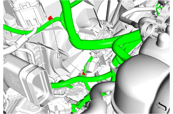
- Wiring Harness Retainer (1) » Remove [2x]
- Electrical Connector (3) » Disconnect
- Wiring Harness (2) » Position aside
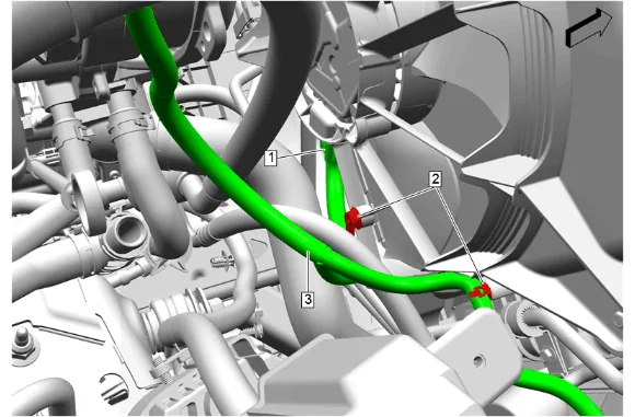
- Wiring Harness Retainer (2) » Remove [2x]
- Electrical Connector (1) » Disconnect
- Wiring Harness (3) » Position aside
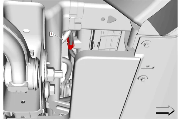
- Engine Oil Cooler Hose Clip (1) » Release
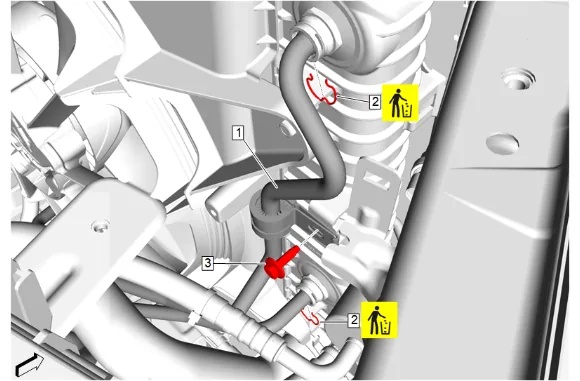
- Engine Oil Cooler Retainer (2) » Remove and DISCARD [2x]
- Engine Oil Cooler Pipe Bracket Bolt (3) » Remove
- Engine Oil Cooler Hose (1) @ Engine Radiator » Remove [2x]
- Cap the ends of the engine oil cooler hose to prevent contamination.
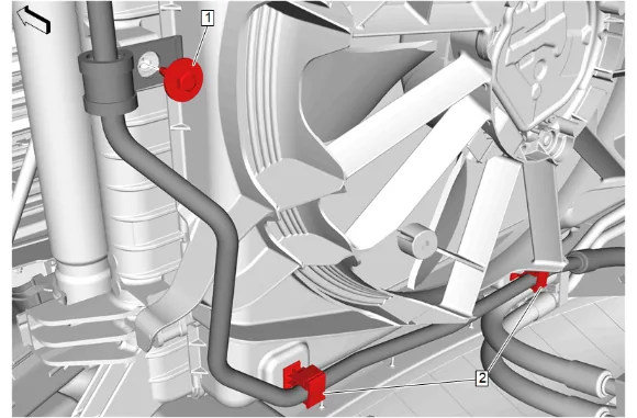
- Transmission Fluid Cooler Pipe Bolt (1) » Remove
- Transmission Fluid Cooler Pipe Clip (2) » Remove [2x]
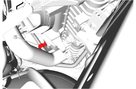
- Transmission Fluid Cooler Pipe Clip (1) » Release
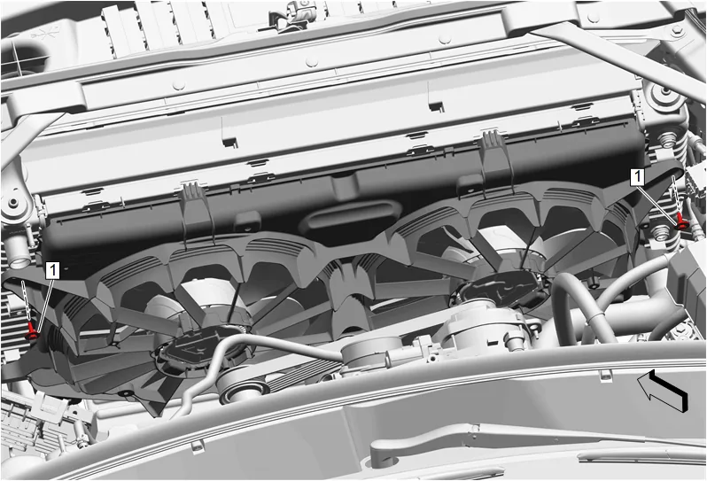
- Engine Coolant Fan Bracket Bolt (1) » Remove [2x]
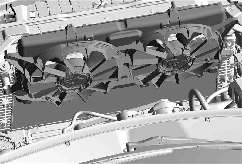
- Engine Cooler Fan (1) @ Engine Radiator » Remove
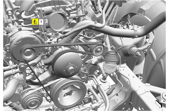
- Using a suitable tool, cut the accessory drive primary belt (1).
- Accessory Drive Primary Belt (1) » Remove and DISCARD
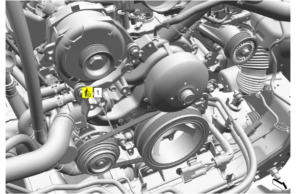
- Using a suitable tool, cut the accessory drive auxiliary belt (1).
- Accessory Drive Auxiliary Belt (1) » Remove and DISCARD
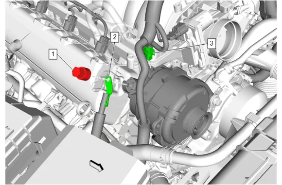
- Battery Positive Cable Nut (1) » Remove
- Starter Solenoid Cable (2) » Remove
- Electrical Connector (3) » Disconnect
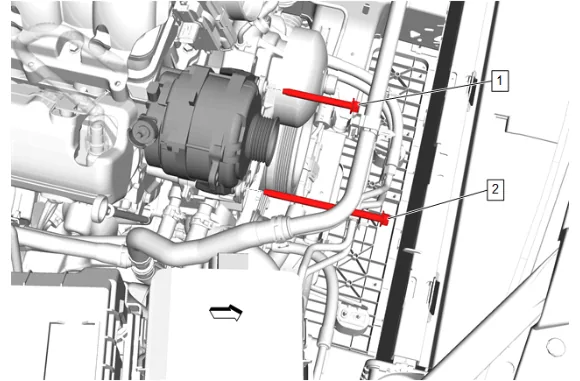
- Generator Bolt (1) » Remove
- Generator Bolt (2) » Remove
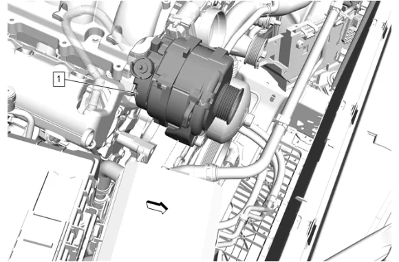
- Generator (1) » Remove
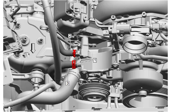
- Hose Clamp (1) » Disengage [2x] — Hose Clamp Replacement Guidelines - Spring Type
- Heater Inlet Hose (2) @ Water Pump » Remove
- Heater Water Auxiliary Pump Hose (3) @ Water Pump » Remove
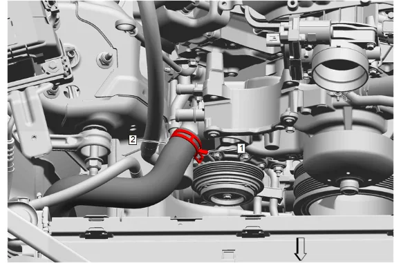
- Hose Clamp (1) » Disengage — Hose Clamp Replacement Guidelines - Spring Type
- Radiator Outlet Hose (2) @ Water Pump » Remove
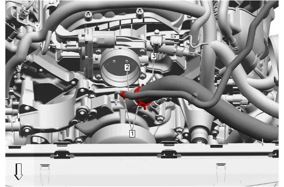
- Hose Clamp (1) » Disengage [2x] — Hose Clamp Replacement Guidelines - Spring Type
- Engine Coolant Air Bleed Hose (2) @ Water Pump » Remove
- Radiator Inlet Hose (3) @ Water Pump » Remove
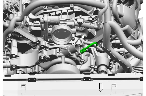
- Engine Coolant Temperature Sensor Electrical Connector (1) » Disconnect
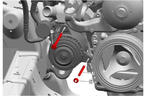
- Air Conditioning Compressor Bolt (1) » Remove
- Air Conditioning Compressor Nut (2) » Remove
- Air Conditioning Compressor Stud (3) » Remove
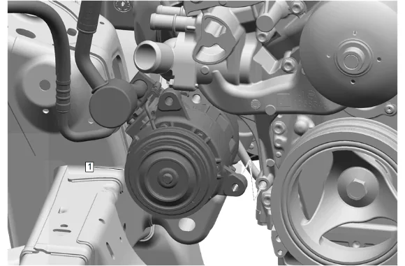
- Air Conditioning Compressor (1) » Remove and position aside
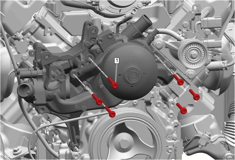
- Water Pump Bolt (1) » Remove [6x]
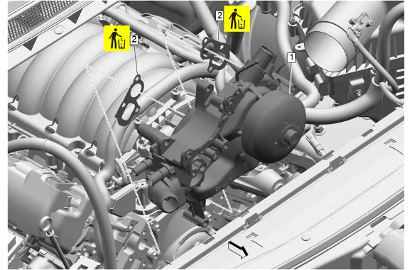
- Water Pump (1) » Remove
- Water Pump Gasket (2) » Remove and DISCARD [2x]
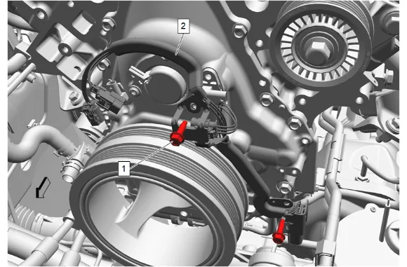
- Disconnect the 4 camshaft position actuator magnet electrical connectors.
- Camshaft Position Sensor Bracket Bolt (1) » Remove [2x]
- Camshaft Position Sensor Wire (2) » Remove Cleaning and Inspection Procedure - Required
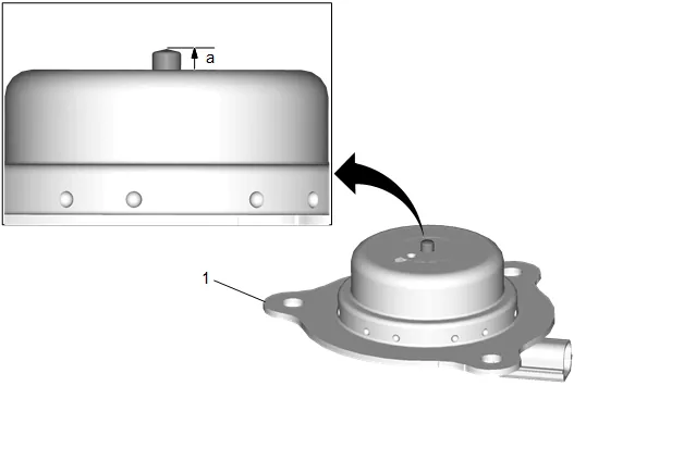
- Inspect the camshaft position (CMP) actuator magnet for the following conditions: 1.1. A damaged electrical connector 1.2. An accumulation of dirt or debris in the recessed area around the pintle. 1.3. A build-up of burnt engine oil on the shaft of the pintle which may cause the pintle to stick and not move freely within the proper range of travel.
- Holding the CMP magnet with the pintle facing upward, measure the pintle retracted position (a). Record the dimension.
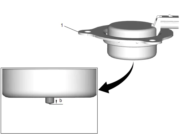
- Holding the CMP magnet with the pintle facing downward, measure the pintle extended position (b). Record the dimension.
- Subtract the retracted dimension (a) from the extended dimension (b) to determine pintle travel. A properly moving pintle will travel 3.0–5.5 mm (0.12–0.22 in).
- If the pintle of the CMP magnet is binding or does not move within the proper range of travel, replace the CMP magnet as an assembly.
-
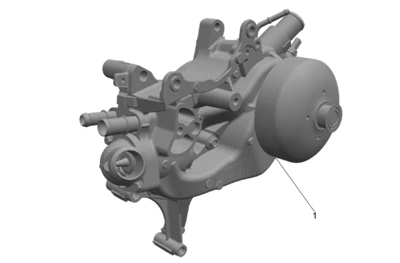
Clean all excess dirt and debris from the water pump (1).
-
Inspect the water pump (1) for the following conditions: 7.1. Water pump gasket and hose sealing surfaces for excessive scratches or gouging 7.2. Restrictions within the internal coolant passages 7.3. Excessive side-to-side play in the pulley shaft 7.4. Leakage at the water inlet housing or rear cover 7.5. Leakage at the water outlet housing or water pump outlet 7.6. Leakage at the water pump vent hole A stain around the vent hole is acceptable. If leakage or dripping occurs with the engine running and the cooling system pressurized, replace the water pump (1). 7.7. Wear or damage in the belt tracking area of the water pump pulley Installation Procedure
-
Camshaft Position Sensor Wire (2) » Install
-
Camshaft Position Sensor Bracket Bolt (1) » Install and tighten [2x] — Fastener Specifications
-
Connect the 4 camshaft position actuator magnet electrical connectors.
-
Water Pump Gasket (2) » Install NEW [2x]
-
Water Pump (1) » Install
-
If NEW threaded components are being installed, loosen the adhesive using a metal pick or similar tool before proceeding. If threaded components are reused, prepare the threaded components using the following steps: 6.1. Remove any loose cured adhesive from the external threads of the component using a lint free cloth. 6.2. Thread the cleaned component into the internal mating threads and remove to loosen trapped cured adhesive. 6.3. Apply thread locking adhesive to the external threads of the component. Adhesives, Fluids, Lubricants, and Sealers 6.4. Ensure there are no gaps in the thread locking adhesive once applied to the component.
-
Water Pump Housing Bolt (1) » Install and hand tighten [6x]
-
Water Pump Housing Bolt (1) » Tighten in sequence [6x] — Fastener Specifications
-
Air Conditioning Compressor (1) » Install
-
Air Conditioning Compressor Stud (3) » Install and tighten — Fastener Specifications
-
Air Conditioning Compressor Nut (2) » Install and tighten — Fastener Specifications
-
Air Conditioning Compressor Bolt (1) » Install and tighten — Fastener Specifications
-
Engine Coolant Temperature Sensor Electrical Connector (1) » Connect
-
Radiator Inlet Hose (3) @ Water Pump » Install
-
Engine Coolant Air Bleed Hose (2) @ Water Pump » Install
-
Hose Clamp (1) » Engage [2x] — Hose Clamp Replacement Guidelines - Spring Type
-
Radiator Outlet Hose (2) @ Water Pump » Install
-
Radiator Outlet Hose Clamp (1) » Engage — Hose Clamp Replacement Guidelines - Spring Type
-
Heater Water Auxiliary Pump Hose (3) @ Water Pump » Install
-
Heater Inlet Hose (2) @ Water Pump » Install
-
Hose Clamp (1) » Engage [2x] — Hose Clamp Replacement Guidelines - Spring Type
-
Generator (1) » Install
-
Generator Bolt (1) » Install and tighten — Fastener Specifications
-
Generator Bolt (2) » Install and tighten — Fastener Specifications
-
Starter Solenoid Cable (2) » Install
-
Battery Positive Cable Nut (1) » Install and tighten — Fastener Specifications
-
Electrical Connector (3) » Connect
- Install the accessory drive auxiliary belt following the instructions included with the belt.
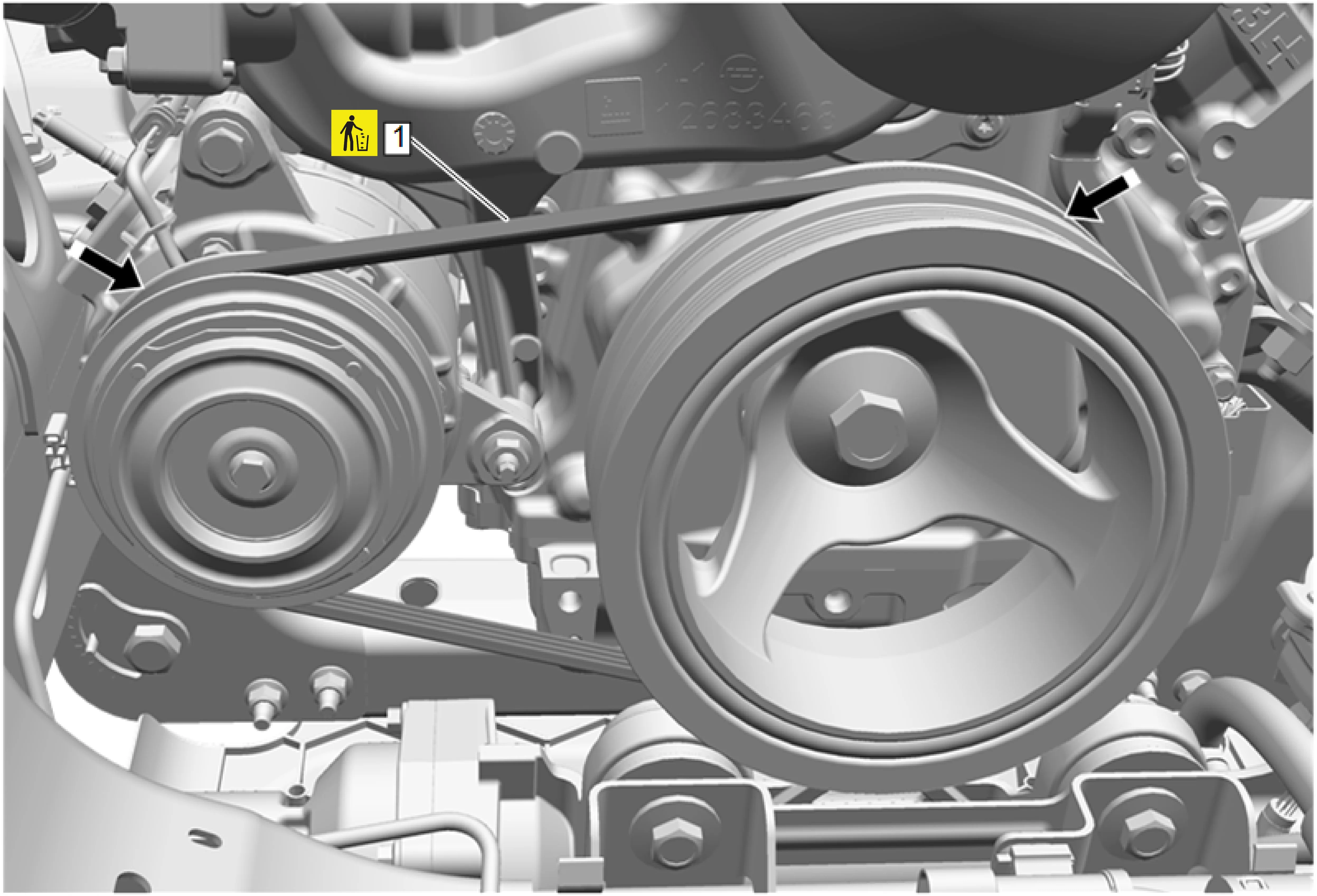
- Inspect the accessory drive auxiliary belt (1) for proper installation and alignment.
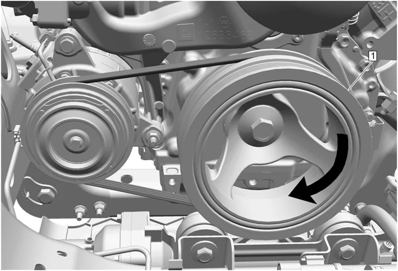
- Rotate the balancer (1) an additional 360 degrees to ensure proper accessory drive auxiliary belt installation.
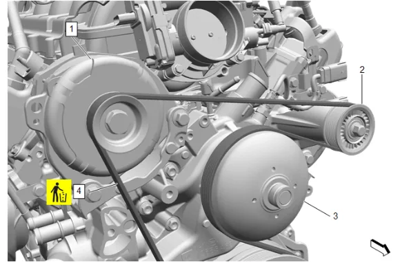
- Position the accessory drive primary belt (4) on the belt idler pulley (2), fan and water pump pulley (3) and generator (1).
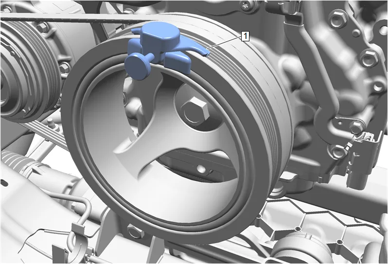
- Install the EN-51767-2 Universal Stretchy Belt Installer (1) onto the crankshaft balancer.
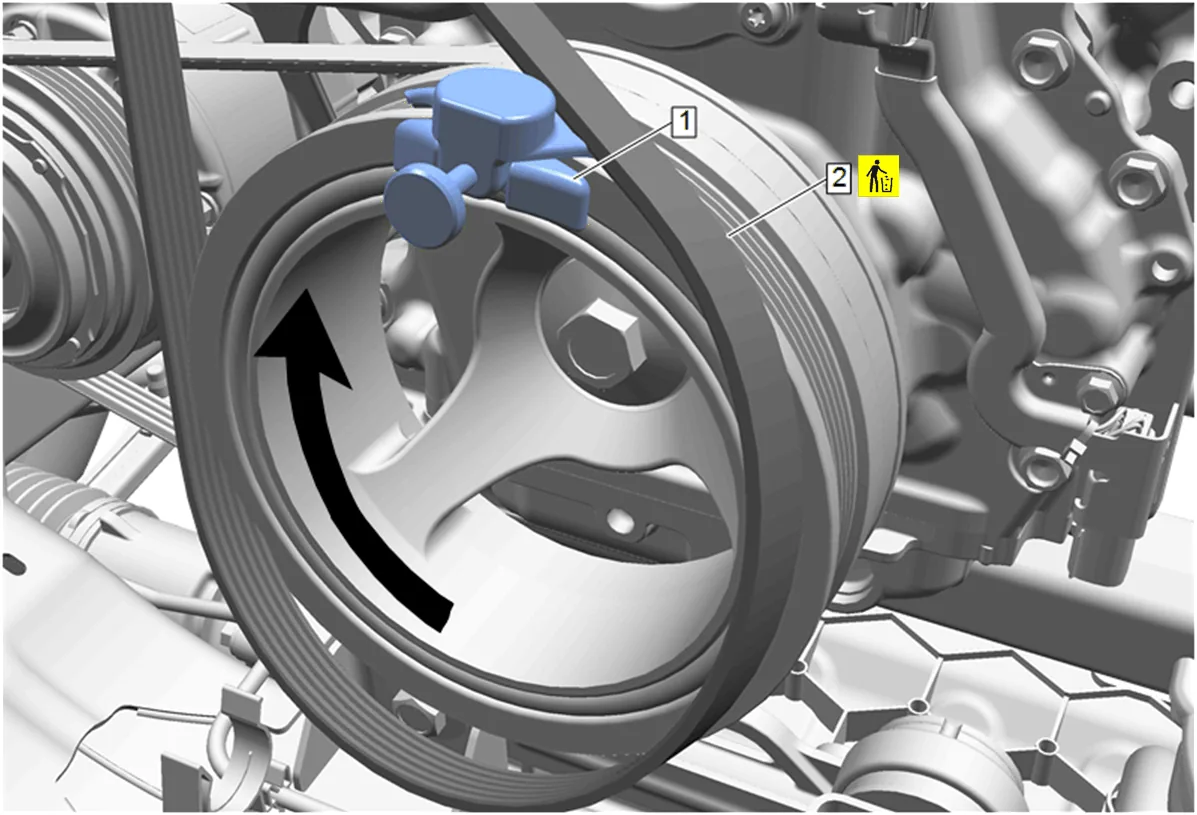
- Position the accessory drive primary belt (2) on the crankshaft balancer.
- Slowly rotate the crankshaft balancer in a clockwise direction until the accessory drive primary belt (2) fully seats on the crankshaft balancer.
- Remove the EN-51767-2 Universal Stretchy Belt Installer (1) from the crankshaft balancer.
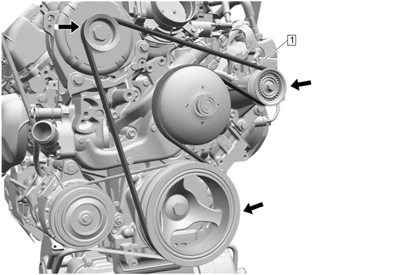
- Inspect the accessory drive primary belt (1) for proper installation and alignment.
-
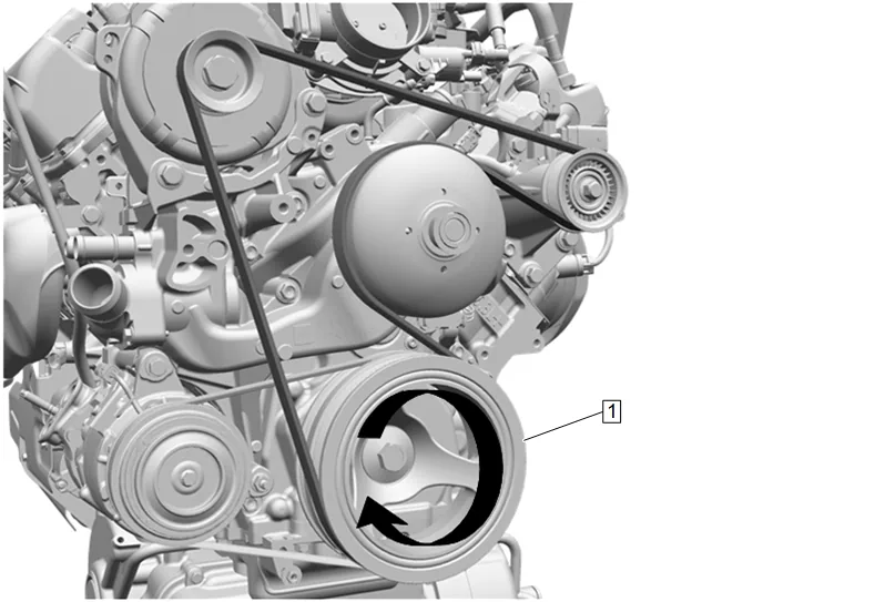
Rotate the crankshaft balancer (1) and additional 360 degrees to ensure proper accessory drive primary belt installation.
-
Engine Cooler Fan (1) @ Engine Radiator » Install
-
Engine Coolant Fan Bracket Bolt (1) » Install and tighten [2x] — Fastener Specifications
-
Transmission Fluid Cooler Pipe Clip (1) » Secure
-
Transmission Fluid Cooler Pipe Clip (2) » Install [2x]
-
Transmission Fluid Cooler Pipe Bolt (1) » Install and tighten — Fastener Specifications
-
Remove the caps on the ends of the engine oil cooler hose to prevent contamination.
-
Engine Oil Cooler Hose (1) @ Engine Radiator » Install [2x]
-
Engine Oil Cooler Pipe Bracket Bolt (3) » Install and tighten — Fastener Specifications
-
Engine Oil Cooler Retainer (2) » Install NEW [2x]
-
Engine Oil Cooler Hose Clip (1) » Secure
- Position the wiring harness. (3)
- Electrical Connector (1) » Connect
- Wiring Harness Retainer (2) » Install [2x]
- Position the wiring harness. (2)
- Electrical Connector (3) » Connect
- Wiring Harness Retainer (1) » Install [2x]
-
Radiator Inlet Hose (3) @ Engine Radiator » Install
-
Radiator Inlet Hose Clamp (1) » Engage — Hose Clamp Replacement Guidelines - Spring Type
-
Radiator Inlet Hose Clip (2) » Install
-
Radiator Surge Tank Outlet Hose (3) » Move into position
-
Radiator Surge Tank Outlet Hose Clip (2) » Install [2x]
-
Air Cleaner Outlet Duct (3) » Install
-
Air Cleaner Outlet Duct Clamp (2) » Tighten [2x] — Fastener Specifications
-
Positive Crankcase Ventilation Fresh Air Tube (1) » Connect — Plastic Collar Quick Connect Fitting Service
-
Air Cleaner Outlet Duct Bracket Bolt (1) » Install and tighten — Fastener Specifications
-
Install the engine wiring harness to the air cleaner outlet duct bracket.
-
Connect the battery negative cable. Battery Negative Cable Disconnection and Connection
-
Fill the cooling system. Cooling System Draining and Filling
-
Start the engine and check for coolant leaks.