Cylinder Leakage Test
Engine Mechanical - 3.0L LM2 Diesel | Diagnostic Information and Procedures | Document ID: 5532163 Special Tools EN-46722 Compression Gauge Adapter Equivalent regional tools: Special Tools Removal Procedure
- Oil Filler Cap » Remove
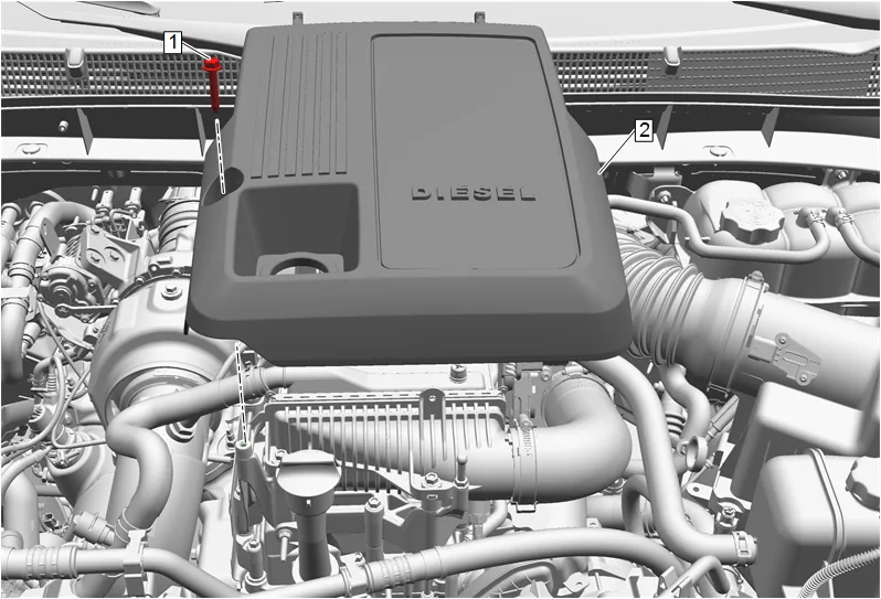
- Intake Manifold Cover Bolt (1) » Remove
- Intake Manifold Cover (2) » Remove
- Install the oil filler cap after removal of the intake manifold cover to prevent debris from falling into the engine.
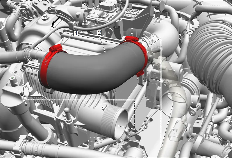
- Charge Air Cooler Outlet Air Hose Clamp (1) » Loosen until disengaged [2x]
- Charge Air Cooler Outlet Air Hose (2) » Remove
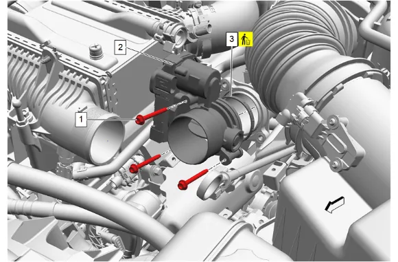
- Disconnect the throttle body electrical connector.
- Throttle Body Bolt (1) » Remove [3x]
- Throttle Body (2) » Remove
- Throttle Body Gasket (3) » Remove and DISCARD
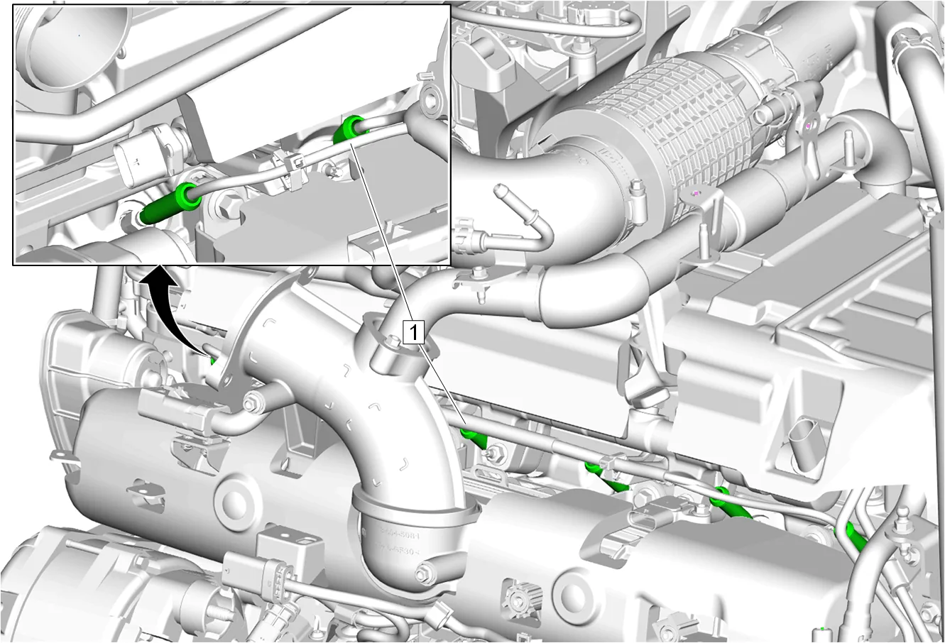
- Electrical Connector (1) @ Glow Plug » Disconnect [6x]
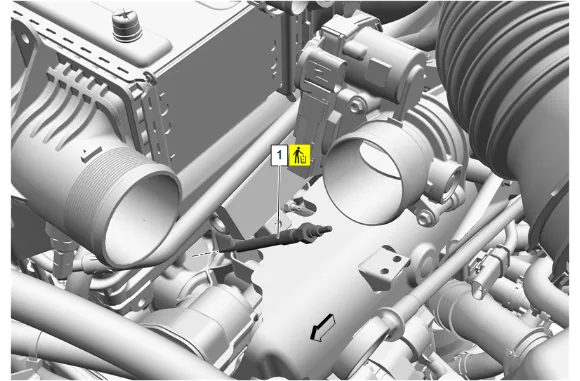
- Glow Plug (1) » Remove and DISCARD [6x]
- Inspect each glow plug tip and ensure the glow plug is not broken. If a broken tip is suspected, inspect the combustion chamber for the glow plug tip. Cleaning and Inspection Procedure - Required
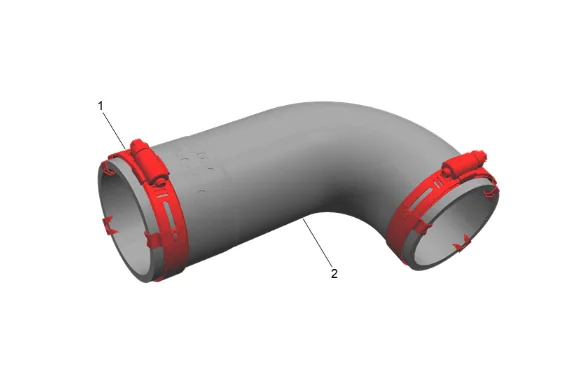
- Inspect the charge air cooler outlet air hose (2): 1.1. Use dish soap and water to clean the inside of the charge air cooler outlet air hose (2). Clean the interior of the hose, and allow to completely dry. Ensure any oil residue is removed from the hose internal interface surfaces. 1.2. Inspect the interior of the charge air cooler outlet air hose (2) for tears or delamination. Replace the hose if damage is found. 1.3. Inspect the charge air cooler outlet air hose clamps (1). Replace the charge air cooler outlet air hose (2) if damage is found or the clamp components are missing. Measurement Procedure
- Rotate the crankshaft to place the piston in the cylinder being tested at top dead center (TDC) of the compression stroke.
- Install a suitable leakdown tester and EN-46722 Compression Gauge Adapter .
- Apply shop air pressure to the tester and adjust according to the manufacturers instructions.
- Record the cylinder leakage value. Cylinder leakage that exceeds 25 percent is considered excessive and may require component service. In excessive leakage situations, inspect for the following conditions: Air leakage sounds at the intake manifold tube, may indicate a worn, stuck or burnt intake valve, broken valve spring, incorrect valve lash or damaged valve train components. Air leakage sounds at the exhaust system tailpipe may indicate a worn, burnt, or stuck exhaust valve, broken valve spring, incorrect valve lash or damaged valve train components. Air leakage sounds from the crankcase, oil level indicator tube, or oil fill tube may indicate worn piston rings, a damaged piston, a worn or scored cylinder bore, a damaged engine block or a damaged cylinder head. Air bubbles in the cooling system may indicate a damaged cylinder head or gasket.
- Remove the leakdown tester and EN-46722 Compression Gauge Adapter .
- Perform the leakage test on the remaining cylinders and record the values. Installation Procedure
-
Glow Plug (1) » Install and tighten [6x] — Fastener Specifications
-
Electrical Connector (1) @ Glow Plug » Connect [6x]
-
Throttle Body Gasket (3) » Install NEW
-
Throttle Body (2) » Install
-
Throttle Body Bolt (1) » Install and tighten [3x] — Fastener Specifications
-
Connect the throttle body electrical connector.
-
Charge Air Cooler Outlet Air Hose (2) » Install
-
Charge Air Cooler Outlet Air Hose Clamp (1) » Tighten [2x] — Fastener Specifications
-
Oil Filler Cap » Remove
-
Intake Manifold Cover (2) » Install
-
Intake Manifold Cover Bolt (1) » Install and tighten — Fastener Specifications
-
Oil Filler Cap » Install