Oscilloscope Diagnostic Kit Description and Operation
Special Tools CH-51450-NVH Oscilloscope Diagnostic Kit (w/NVH) EL-47966 Multi Diagnostic Interface MDI Equivalent regional tools. Special Tools and Equipment The CH-51450-NVH Oscilloscope Diagnostic Kit (w/NVH) is an automotive oscilloscope which receives input from an attached accelerometer and displays all input frequencies on a laptop or tablet computer. The vibration concern frequency(ies) are obtained through the use of the CH-51450-NVH Oscilloscope Diagnostic Kit (w/NVH) hardware, while vehicle component speed data is gathered through the EL- 47966 Multi Diagnostic Interface MDI. The MDI data is integrated into the Oscilloscope software so that vibration(s) can be tied to specific vehicle components based on their speed to determine the source of the vibration concern. Oscilloscope Inputs The CH-51450-TA183 Accelerometer incorporates a 3 m (9.8 ft) cord that allows the sensor to be placed on virtually any component of the vehicle where a vibration concern is felt. The Accelerometer uses a self-powered NVH interface module. The NVH interface module uses a replaceable battery. Input B is the default port for a single accelerometer. The cord used to connect the NVH interface module to the CH-51450-NVH Oscilloscope is 5 m (16.4 ft) long. Input D is used for the CH-51450-TA186 Optical Tachometer Sensor which is used during driveline balancing. It incorporates a 2.5 m (8.2 ft) cord and a 5 m (16.4 ft) cord. There is also an optional microphone that can be used with the CH-51450-NVH Oscilloscope. Oscilloscope Accelerometer Placement Proper placement of the CH-51450-TA183 Accelerometer is critical to ensure that proper vibration readings are obtained by the CH-51450-NVH Oscilloscope. The CH-51450-TA183 Accelerometer should be placed on the drivers side inboard seat track. Once a baseline reading has been taken, the CH-51450-TA183 Accelerometer can be placed on the point of the customer concern to verify what the customer is hearing or feeling. Oscilloscope Accelerometer-to-Component Attachment

When the NVH software is first opened and the NVH tab is selected, there is a set-up wizard within the CH-51450-NVH NVH software which has a step-by-step guide to ensure the CH-51450- NVH Oscilloscope and MDI are connected correctly, and to input the vehicle information. Oscilloscope NVH Display The CH-51450-NVH Oscilloscope display consists of three tabs:
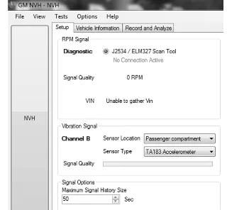
The first tab is set-up. The set-up information can be entered here if not already done through the set-up wizard. It can also be updated here, if necessary. A laptop or desktop computer, EL-47966 Multi Diagnostic Interface MDI, CH-51450-NVH Oscilloscope, CH-51450-TA148 NVH interface, and CH-51450-TA183 Accelerometer are needed to do a vibration analysis.
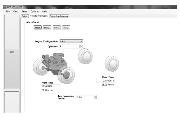
The second tab is vehicle information. The vehicle information can be entered here if not already done through the set-up wizard. It can also be updated here, if necessary.
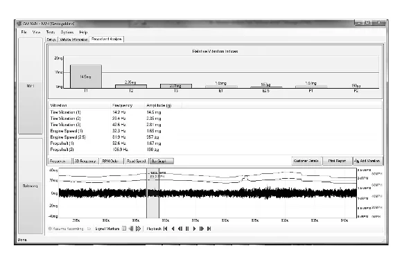
The third tab is the record and analyze tab. The standard display will show the known input frequencies received from the CH-51450-TA183 Accelerometer as a bar graph at the top of the screen. At the middle of the screen, the input frequencies are listed as text. The frequency(ies) are displayed in Hertz (Hz). If desired, the frequency(ies) can be displayed in RPM by clicking Options, then Advanced Options. The actual amplitude strength of each frequency is displayed and shown in g’s of acceleration (expressed to the thousandth of a force of gravity, or “milli-g”). At the bottom of the screen, it also shows a plot of all frequency inputs along with engine speed in blue, and vehicle speed in red. The data can be saved in 50 second increments. The data can then be saved by clicking File, then Save. Files that are saved can then be loaded into the software by clicking File, then Load. Oscilloscope Balancing The CH-51450-NVH Oscilloscope with balancing software can be used to identify some rotating component/systems which exhibit imbalance if the component rotational speed is the dominant frequency of the vibration concern. The CH-51450-NVH Oscilloscope is used with the CH-51450- TA186 Optical Tachometer Sensor. The CH-51450-TA186 Optical Tachometer Sensor directly measures component rotational speed so a known weight can be added for a baseline reading. Then the oscilloscope will determine where to add a specific amount of weight to the component. For example, the CH-51450-NVH Oscilloscope can be used to balance the driveline on rear wheel drive and all wheel drive vehicles. The methods that can be employed are a tuned weight approach for drivelines that use couplers and a dual hose clamp approach for drivelines that use CV or two-axis universal joints. The balancing process consists of the CH-51450-TA186 Optical Tachometer Sensor to directly read the driveline speed and software that directs where the weights should be placed depending on the type of driveline/propeller shaft being balanced. Oscilloscope Balancing Software Set-up
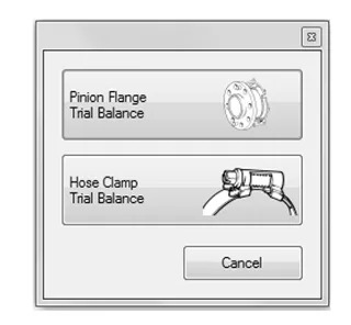
When the NVH software is first opened and the Balancing tab is selected, a pop-up box within the CH-51450-NVH balancing software will ask which type of balancing method is to be used. The two methods are pinion flange or hose clamp. Then either the wizard (which will walk through the connections and input data) or advanced configuration can be chosen to input the initial information and start the balancing procedure. Oscilloscope Balancing Display The propeller shaft balancing will consist of an initial run, three calibration runs, and a verification run. The software will walk through what is required for each run.
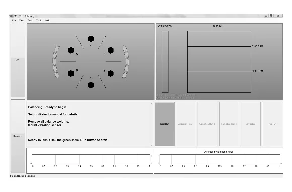
An example of the pinion flange balancing screen is shown above.
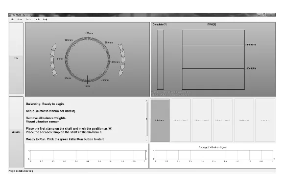
An example of the hose clamp balancing screen is shown above.