Driveline System Balance Adjustment
Special Tools CH-51450-NVH Oscilloscope Diagnostic Kit (w/NVH) EL-38792-A Electronic Vibration Analyzer (EVA) 2 EL-38792-20 20-Foot Timing Light Power Cord Extension EL-38792-25 Inductive Pickup Timing Light EL-38792-27 6-Foot EVA Power Cord Extension For equivalent regional tools. Special Tools and Equipment This procedure is designed to fine-tune the balance of a propeller shaft while it is mounted in the vehicle. Small amounts of residual imbalance which could be present in other related driveline system components could be compensated for as a result of performing this procedure. The end result of properly fine-tuning a propeller shaft balance may be either a significant reduction or an elimination of a vibration disturbance that is related to the first-order rotation of a propeller shaft. Fine-tuning the balance of a propeller shaft can aid in achieving a more balanced total driveline system.
- Raise and support the vehicle; ensure that the drive axle or axles are supported at ride height – vehicle body supported by suspension components. Lifting and Jacking the Vehicle
- Connect the Oscilloscope to the USB port of the computer using the blue USB cable, CH- 51450-M1106.
- Connect the Accelerometer CH-51450-TA183 to the NVH Interface CH-51450-TA148.
- Connect the NVH Interface to Channel B of the Oscilloscope using the CH-51450-TA098 BNC to BNC cable.
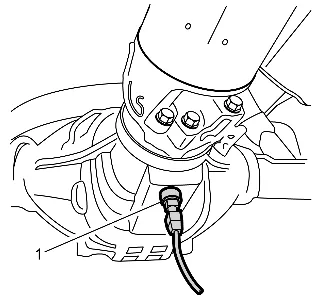
- Mount the Accelerometer (1) to a suitable surface on the vehicle differential. If the differential case is non-ferrous, a steel washer can be glued on the differential case in order to secure the magnetic Accelerometer.
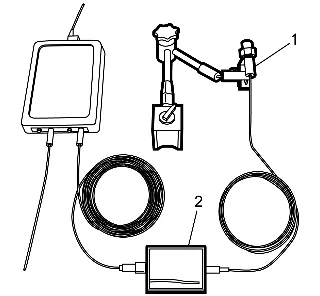
- Connect the Optical Sensor CH-51450-TA186 (1) to the Optical Sensor Interface CH-51450- TA185 (2).
- Connect the Optical Sensor Interface to Channel D of the Oscilloscope using the CH-51450- TA098 BNC to BNB cable.
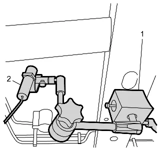
- Mount the Magnetic Mounting Fixture CH-51450-TA187 (1) to a suitable surface on the vehicle underbody.
- Place a ½ inch strip of reflective tape to the propeller shaft.
- Focus the laser (2) on the reflective tape.
- Install 2 hose clamps side by side to the propeller shaft near the differential, on an area clear of any factory balance weights.
- Mark the excess band on the hose clamps.
- Remove the hose clamps and trim the excess from the hose clamp bands.
- Enter the weight of the hose clamp, in grams, into the balancing software.
- To determine the weight of the hose clamp, use the following: Cut the screw body off of the clamp, even with end of the screw. Weigh the screw body on a gram scale (14 g is typical).
- Measure the circumference of the propeller shaft near the hose clamps using the supplied ruler and enter that figure, in millimeters, into the balancing software.
- Alternatively, enter the diameter, in millimeters, of the propeller shaft into the balancing software.
- Before beginning the test, inspect for the following: The vehicle is properly supported. Lifting and Jacking the Vehicle Remove any rocks or debris embedded in the tire treads. Secure all test leads clear of rotating components. Disable the ABS and traction control, if equipped. Turn OFF the A/C, and any other accessories.
- Determine a suitable propeller shaft speed. Start the engine. Place the transmission in the highest forward gear. Run the engine to highway speed, typically 104-112 km/h (65-70 mph). When the RPM can be held stable for longer than 3 seconds, the balancing software will capture and enter the propeller shaft speed. Alternatively, click the Edit Manually check box and enter the desired propeller shaft speed. Place the transmission in NEUTRAL. Turn OFF the engine.
- Begin the propeller shaft balancing. Initial Run
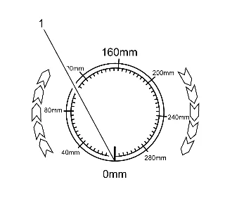
20.1. Place the first clamp on the propeller shaft near the differential. 20.2. Clearly mark the location of the clamp as reference for all remaining measurements. 20.3. Label the mark (1) as 0 mm. 20.4. Measure the distance specified by the software and place the second clamp next to the first clamp. 20.5. Measure the distance specified by the software and place the second clamp next to the first clamp. 20.6. Press the green Initial Run button to start the test. 20.7. Start the engine. 20.8. Place the transmission in the highest forward gear. 20.9. Accelerate the engine until the required speed is reached. 20.10. The RPM graph will highlight green when the RPM is within the specified range, and data will only be gathered while within this range. 21. When the Complete % bar graph is filled, place the transmission in NEUTRAL and turn OFF the engine. 22. Perform the first calibration run. Calibration Run 1 22.1. Place both hose clamps at the 0 mm label. 22.2. Press the green Calibration Run 1 button. 22.3. Start the engine. 22.4. Place the transmission in the highest forward gear. 22.5. Accelerate the engine until the required speed is reached. 23. When the Complete % bar graph is filled, place the transmission in NEUTRAL and turn OFF the engine. 24. Perform the second calibration run. Calibration Run 2 24.1. Measuring in the direction of forward propeller shaft rotation, mark the point as indicated on the balancing software. 24.2. Place both hose clamps at this mark. 24.3. Press the green Calibration Run 2 button. 24.4. Start the engine. 24.5. Place the transmission in the highest forward gear. 24.6. Accelerate the engine until the required speed is reached. 25. When the Complete % bar graph is filled, place the transmission in NEUTRAL and turn OFF the engine. 26. Perform the third calibration run. Calibration Run 3 26.1. Measuring from the 0 mm mark in the direction of forward propeller shaft rotation, mark the point as indicated on the balancing software. 26.2. Place both hose clamps at this mark. 26.3. Press the green Calibration Run 3 button. 26.4. Start the engine. 26.5. Place the transmission in the highest forward gear. 26.6. Accelerate the engine until the required speed is reached. 27. When the Complete % bar graph is filled, place the transmission in NEUTRAL and turn OFF the engine. 28. Perform the final propeller shaft balancing. Final Balance 28.1. Measure and mark the locations as indicated on the balancing software. 28.2. Place the hose clamps at these locations. 28.3. Press the green Verification button. 28.4. Start the engine. 28.5. Place the transmission in the highest forward gear. 28.6. Accelerate the engine until the required speed is reached. 29. When the Complete % bar graph is filled, place the transmission in NEUTRAL and turn OFF the engine. 30. The software will display the final imbalance. 31. If the imbalance exceeds the minimum requirement, the software will recommend removing the rear tire and wheel assemblies and, after securing the brake rotors or brake drums, restarting the test. Pinion Flange Method
- Raise and support the vehicle; ensure that the drive axle or axles are supported at ride height – vehicle body supported by suspension components. Lifting and Jacking the Vehicle
- Connect the Oscilloscope to the USB port of the computer using the blue USB cable, CH- 51450-M1106.
- Connect the Accelerometer CH-51450-TA183 to the NVH Interface CH-51450-TA148.
- Connect the NVH Interface to Channel B of the Oscilloscope using the CH-51450-TA098 BNC to BNC cable.
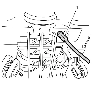
-
Mount the Accelerometer (1) to a suitable surface near the front of the differential. If the surface is non-ferrous, a steel washer can be glued to the surface in order to secure the magnetic Accelerometer.
-
Connect the Optical Sensor CH-51450-TA186 (1) to the Optical Sensor Interface CH-51450- TA185 (2).
-
Connect the NVH Interface to Channel D of the Oscilloscope using the CH-51450-TA098 BNC to BNB cable.
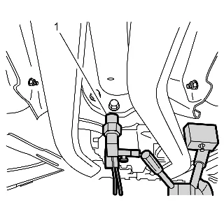
- Mount the Magnetic Mounting Fixture CH-51450-TA187 (1) to a suitable surface on the vehicle underbody.
- Place a ½ inch strip of reflective tape to the propeller shaft.
- Focus the laser on the reflective tape.
- Measure the circumference of the pinion flange bolt circle and enter that figure, in millimeters, into the balancing software.
- Alternatively, enter the diameter, in millimeters, of the pinion flange into the balancing software.
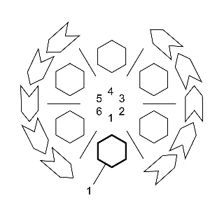
- Enter the number of pinion flange bolts into the balancing software.
- Number the pinion flange bolts and/or studs (1) in the direction of propeller shaft rotation.
- Before beginning the test, inspect for the following: The vehicle is properly supported. Lifting and Jacking the Vehicle Remove any rocks or debris embedded in the tire treads. Secure all test leads clear of rotating components. Disable the ABS and traction control, if equipped. Turn OFF the A/C, and any other accessories.
- Determine a suitable propeller shaft speed. Start the engine. Place the transmission in the highest forward gear. Run the engine to highway speed, typically 104-112 km/h (65-70 mph). When the RPM can be held stable for longer than 3 seconds, the balancing software will capture and enter the propeller shaft speed. Alternatively, click the Edit Manually check box and enter the desired propeller shaft speed. Place the transmission in NEUTRAL. Turn OFF the engine.
- Begin balancing the propeller shaft. Initial Run 17.1. Press the green Initial Run button to start the test. An initial measurement of the propeller shaft will be taken. 17.2. Start the engine. 17.3. Place the transmission in the highest forward gear. 17.4. Accelerate the engine until the required speed is reached. 17.5. The RPM graph will highlight green when the RPM is within the specified range, and data will only be gathered while within this range.
- When the Complete % bar graph is filled, place the transmission in NEUTRAL and turn OFF the engine.
- Perform the first calibration run. Calibration Run 1 19.1. Place 4.5 g of weight at location 1 by stacking 3 of the balancing weights (1.5 g each). The weights may be affixed to the front or the rear of the pinion flange. 19.2. Press the green Calibration Run 1 button. 19.3. Start the engine. 19.4. Place the transmission in the highest forward gear. 19.5. Accelerate the engine until the required speed is reached.
- When the Complete % bar graph is filled, place the transmission in NEUTRAL and turn OFF the engine.
- Perform the second calibration run. Calibration Run 2 21.1. Remove the balancing weights from location 1. 21.2. Install the balancing weights at location 3. 21.3. Press the green Calibration Run 2 button. 21.4. Start the engine. 21.5. Place the transmission in the highest forward gear. 21.6. Accelerate the engine until the required speed is reached.
- When the Complete % bar graph is filled, place the transmission in NEUTRAL and turn OFF the engine.
- Perform the third calibration run. Calibration Run 3 23.1. Remove the balancing weights from location 3. 23.2. Install the balancing weights at location 5. 23.3. Press the green Calibration Run 3 button. 23.4. Start the engine. 23.5. Place the transmission in the highest forward gear. 23.6. Accelerate the engine until the required speed is reached.
- When the Complete % bar graph is filled, place the transmission in NEUTRAL and turn OFF the engine.
- Perform the final propeller shaft balancing. Final Balance 25.1. Remove the balancing weights from location 5. 25.2. Install the balancing washers to the location(s) indicated by the balancing software. 25.3. Press the green Verification button. 25.4. Start the engine. 25.5. Place the transmission in the highest forward gear. 25.6. Accelerate the engine until the required speed is reached.
- When the Complete % bar graph is filled, place the transmission in NEUTRAL and turn OFF the engine..
- The software will display the final imbalance.
- If the imbalance exceeds the minimum requirement, the software will recommend removing the rear tire and wheel assemblies and, after securing the brake rotors or brake drums, and restarting the test.
- If the test is to be restarted, remove all of the balancing weights.
- The test can then be restarted by either of the following methods: Press the Initial Run button to restart the test. Press the Balancing button to enter the test through the setup wizard. Adjustment Procedure Using EVA
- Raise and support the vehicle; ensure that the drive axle or axles are supported at ride height – vehicle body supported by suspension components. Lifting and Jacking the Vehicle
- With the tire and wheel assemblies, and the brake rotors and/or brake drums removed from the drive axle, or axles, start the engine and turn OFF all engine accessories.
- Place the transmission in forward gear.
- Run the vehicle at the speed which causes the most vibration in the propeller shaft; observe which end of the propeller shaft exhibits the greatest amount of vibration disturbance.
- Turn the engine OFF to slow and stop the rotation of the propeller shaft.
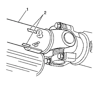
- Mark the circumference of the propeller shaft (1) to be balanced at four points 90 degrees apart (2), nearest the end that exhibited the greatest amount of vibration. Number the marks 1–4.
- Install the EL-38792-A EVA 2, the EL-38792-27 6-foot EVA power cord extension, the EL- 38792-25 inductive pickup timing light, or equivalent, and the EL-38792-20 20-foot extension to the vehicle.
- Connect the clip of the EL-38792-25 inductive pickup timing light, or equivalent, onto the trigger wire of the EL-38792-A EVA 2.
- Mount the EL-38792-A EVA 2 vibration sensor to the bottom of the driveline component nearest to the end of the propeller shaft that exhibited the greatest amount of vibration. Ensure that the side of the sensor marked UP faces upward and that the sensor is positioned as close to horizontal as possible.
- Plug the vibration sensor cord into Input A of the EL-38792-A EVA 2. Input B is not used with the strobe function.
- Run the vehicle at the speed which causes the most vibration in the propeller shaft; observe the frequency readings displayed on the EL-38792-A EVA 2.
- Verify that the dominant frequency displayed on the EL-38792-A EVA 2 matches the recorded frequency of the vibration concern.
- Record the amplitude reading of the dominant frequency displayed.
- Using the strobe function of the EL-38792-A EVA 2, select the correct filter range to use for the balance adjustment, so that the dominant frequency would be near the middle of the filter range. Use the full range filter only as a last resort if one of the specific range filters will not cover the frequency adequately.
- The EL-38792-A EVA 2 display will show the dominant frequency, the amplitude and the selected filter range.
- Aim the EL-38792-25 inductive pickup timing light, or equivalent, at the marks placed on the propeller shaft. When activated, the strobe effect will appear to freeze the marks placed on the rotating propeller shaft. Record which of the numbered marks appears to be at the bottom of the propeller shaft, or the 6 o’clock position. This position identifies the light spot of the propeller shaft.
- Turn the engine OFF to slow and stop the rotation of the propeller shaft.
- Install a band-type hose clamp as a weight, with the head of the clamp directly on the light spot.
- Run the vehicle at the speed which causes the most vibration in the propeller shaft.
- Using the EL-38792-25 inductive pickup timing light, or equivalent, observe the positioning of the marks placed on the propeller shaft.
- If the marks on the propeller shaft now appear to move erratically, compare the current amplitude of the vibration frequency to the original amplitude recorded previously. If the amplitude has decreased from the amplitude recorded, the balance achieved may be sufficient and the vehicle should be road tested to determine the effect on the vibration concern.
- If the clamp head over the original light spot, is now near the top of the propeller shaft, within 180 degrees – near or below the 12 o’clock position – of the original position at the bottom of the propeller shaft – 6 o’clock position – the position of the weight needs adjusting. Perform the following steps: 22.1. Move the position of the clamp head toward the 6 o’clock position. 22.2. Using the EL-38792-25 inductive pickup timing light, or equivalent, recheck the positioning of the propeller shaft marks. 22.3. If necessary, continue to move the position of the clamp head toward the 6 o’clock position and recheck progress until an improvement in balance is achieved.
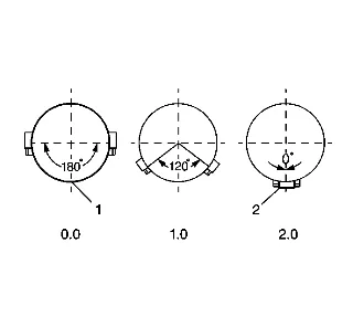
- If the clamp head over the original light spot, is still positioned at the bottom of the propeller shaft – 6 o’clock position – additional weight is required. Perform the following steps: 23.1. Add a second clamp to the propeller shaft, next to the first clamp and with the clamp heads aligned. 23.2. Using the EL-38792-25 inductive pickup timing light, or equivalent, recheck the positioning of the propeller shaft marks. 23.3. If the clamp heads over the original light spot, are now 90–180 degrees – at or above the 9 o’clock or the 3 o’clock positions – from the original position at the bottom of the propeller shaft – 6 o’clock position (1) – less total weight is required. Proceed to step 23.4. 23.4. Move the position of the clamp heads an equal distance on either side of the light spot between 1 and 120 degrees apart from each other to reduce the total amount of weight in relation to the light spot. 23.5. Using the EL-38792-25 inductive pickup timing light, or equivalent, recheck the positioning of the propeller shaft marks. 23.6. If necessary, continue to move the position of the clamp heads an equal distance on either side of the light spot to a maximum of 120 degrees apart from each other, until the greatest improvement to balance is achieved. 23.7. If improvement has been made to the balance of the propeller shaft, but the balance is still not satisfactory, still more total weight may be required. Perform the following steps: 23.7.1. Add a third clamp to the propeller shaft, next to the first and second clamps and with the clamp head directly (2) on the light spot. 23.7.2. Move the position of the first and second clamp heads an equal distance on either side of the light spot between 1 and 120 degrees apart from each other to arrive at a total amount of weight greater than two weights, but less than three weights in relation to the light spot. 23.7.3. Using the EL-38792-25 inductive pickup timing light, or equivalent, recheck the positioning of the propeller shaft marks. 23.7.4. If necessary, continue to move the position of the first and second clamp heads an equal distance on either side of the light spot to a maximum of 120 degrees apart from each other, until the greatest improvement to balance is achieved. 23.8. If a third clamp was used on the propeller shaft and sufficient balance could still not be achieved, the propeller shaft requires replacement.
- If the clamp head over the original light spot is now 90–180 degrees – at or above the 9 o’clock or the 3 o’clock positions – from the original position at the bottom of the propeller shaft – 6 o’clock position – less total weight is required. Perform the following steps: 24.1. Add a second clamp to the propeller shaft, next to the first clamp and with the clamp heads aligned. 24.2. Move the position of the clamp heads an equal distance on either side of the light spot between 120 and 180 degrees apart from each other to reduce the total amount of weight in relation to the light spot. 24.3. Using the EL-38792-25 inductive pickup timing light, or equivalent, recheck the positioning of the propeller shaft marks. 24.4. If necessary, continue to move the position of the clamp heads an equal distance on either side of the light spot to a maximum of 180 degrees apart from each other, but not less than 120 degrees apart, until the greatest improvement to balance is achieved.
- If the marks on the propeller shaft now appear to move erratically, compare the current amplitude of the vibration frequency to the original amplitude recorded previously. If the amplitude has decreased from the amplitude recorded, the balance achieved may be sufficient and the vehicle should be road tested to determine the effect on the vibration concern. Adjustment Procedure Without Oscilloscope or EVA
- Raise and support the vehicle; ensure that the drive axle, or axles are supported at ride height – vehicle body supported by suspension components.
- With the tire and wheel assemblies, and the brake rotors and/or brake drums removed from the drive axle or axles, start the engine and turn OFF all engine accessories.
- Place the transmission in forward gear.
- Run the vehicle at the speed which causes the most vibration in the propeller shaft; observe which end of the propeller shaft exhibits the greatest amount of vibration disturbance.
- Carefully hold a piece of chalk up to the end of the propeller shaft in order to just make contact as the shaft rotates.
- Turn the engine OFF to slow and stop the rotation of the propeller shaft.
- Observe the location of the chalk mark on the propeller shaft. If the chalk mark circles the entire propeller shaft after the first attempt, remove the mark from the shaft and repeat steps 2 through 7; touch the chalk more gently to the propeller shaft. If the chalk mark circles the entire propeller shaft after the second attempt, runout of the propeller shaft may not be the cause of the disturbance. Proceed to step 16. If the chalk mark is only on a small portion of the propeller shaft, the mark identifies the heavy spot of the propeller shaft. The heavy spot of the propeller shaft will deflect downward during rotation. Place a small mark on the shaft 180 degrees, directly opposite the heavy spot, and identify the mark as the light spot. Proceed to step 8. 8. Install a band-type hose clamp to the propeller shaft as a weight, with the head of the clamp directly on the light spot, or 180 degrees, directly opposite the heavy spot.
- Observe the amount of disturbance to the propeller shaft. If the amount of disturbance to the propeller shaft appears to be significantly reduced, the balance achieved may be sufficient and the vehicle should be road tested to determine the effect on the vibration concern. The head of the clamp can be moved very slightly, if necessary to refine the balance achieved. If the amount of disturbance to the propeller shaft appears to be almost unchanged or even increased, proceed to step 10.
- Add a second clamp to the propeller shaft, next to the first clamp and with the clamp heads aligned.
- Observe the amount of disturbance to the propeller shaft. If the amount of disturbance to the propeller shaft appears to be significantly reduced, the balance achieved may be sufficient and the vehicle should be road tested to determine the effect on the vibration concern. The head of the clamps can be moved very slightly an equal distance apart on either side of the light spot, or moved slightly while still aligned, if necessary to refine the balance achieved. If the amount of disturbance to the propeller shaft appears to be almost unchanged or even increased, proceed to step 12.
- Move the position of the clamp heads an equal distance on either side of the light spot between 1 and 120 degrees apart from each other to reduce the total amount of weight in relation to the light spot.
- Observe the amount of disturbance to the propeller shaft. If the amount of disturbance to the propeller shaft appears to be significantly reduced, the balance achieved may be sufficient and the vehicle should be road tested to determine the effect on the vibration concern. If necessary, continue to move the position of the clamp heads an equal distance on either side of the light spot to a maximum of 120 degrees apart from each other, until the greatest amount of reduction in the vibration disturbance is achieved. If the amount of disturbance to the propeller shaft appears to be almost unchanged or even increased, proceed to step 14.
- Add a third clamp to the propeller shaft, next to the first and second clamps and with the head of the clamp directly on the light spot.
- Observe the amount of disturbance to the propeller shaft. If the amount of disturbance to the propeller shaft appears to be significantly reduced, the balance achieved may be sufficient and the vehicle should be road tested to determine the effect on the vibration concern. If necessary, continue to move the position of the first and second clamp heads an equal distance on either side of the light spot to a maximum of 120 degrees apart from each other, until the greatest amount of reduction in the vibration disturbance is achieved. If the amount of disturbance to the propeller shaft appears to be almost unchanged or even increased after a third clamp was used on the propeller shaft, the propeller shaft likely requires replacement.
- If the heavy spot of the propeller shaft could not be identified, install a band-type hose clamp to the propeller shaft as a weight, with the head of the clamp directly in-line with an existing factory-installed weight.
- Observe the amount of disturbance to the propeller shaft. If the amount of disturbance to the propeller shaft appears to be significantly reduced, the balance achieved may be sufficient and the vehicle should be road tested to determine the effect on the vibration concern. The head of the clamp can be moved very slightly, if necessary to refine the balance achieved. If the amount of disturbance to the propeller shaft appears to be almost unchanged or even increased, proceed to step 18.
- Move the head of the clamp 180 degrees, directly opposite the factory-installed weight.
- Observe the amount of disturbance to the propeller shaft. If the amount of disturbance to the propeller shaft appears to be significantly reduced, the balance achieved may be sufficient and the vehicle should be road tested to determine the effect on the vibration concern. The head of the clamp can be moved very slightly, if necessary to refine the balance achieved. If the amount of disturbance to the propeller shaft appears to be almost unchanged or even increased, the propeller shaft may require replacement.