Compressor Air Intake Turbocharger System Description
Engine Controls and Fuel - 3.0L LM2 Diesel | Description and Operation | Document ID: 5207775 Turbocharger Vane Position Actuator
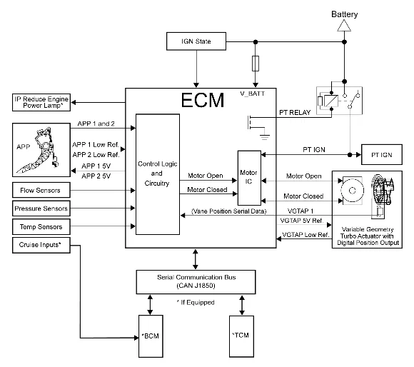
A turbocharger increases engine power by pumping compressed air into the combustion chambers, allowing a greater quantity of fuel to combust at the optimal air/fuel ratio. The Variable Geometry Turbine (VGT) body assembly contains a contact-less inductive VGT position sensing element that is managed by a customized integrated circuit. The VGT position sensor is mounted within the VGT body assembly and is not serviceable. The engine control module (ECM) supplies the VGT body with a 5 V reference circuit, a low reference circuit, an H-bridge motor directional control circuit, and an asynchronous signal/serial data circuit. The asynchronous signal means communication is only going from the VGT body to the ECM. The VGT body cannot receive data from the ECM over the signal/serial data circuit. The VGT position sensor provides a signal voltage that changes relative to VGT vanes angle. The customized integrated circuit translates the voltage based position information into serial data using the Society of Automotive Engineers (SAE) J2716 Single Edge Nibble Transmission (SENT) protocol. The VGT position sensor information is transmitted between the VGT body and the ECM on the signal/serial data circuit. The ECM decodes the serial data signal and is used as voltages for VGT position sensor. The turbocharger vanes are normally closed at idle, greater than 70%, when the engine is not under load. As the vehicle accelerates and the torque request stabilizes, the ECM will open the turbocharger vanes to regulate boost pressure. The ECM will often close the turbocharger vanes to create back pressure to drive exhaust gas through the Exhaust Gas Recirculation (EGR) valve as required. At extreme cold temperatures, the ECM may maintain a more closed vane position, at low load conditions, in order to accelerate engine coolant heating. The Charged Air Cooler or Turbocharger Intercooler The turbocharger is supported by an air-to-water charge air cooler system, which uses fresh air drawn through a heat exchanger to reduce the temperature of the warmer compressed air forced through the intake system. Inlet air temperature can be reduced by up to 100°C (180°F), which enhances performance. This is due to the higher density of oxygen in the cooled air, which promotes optimal combustion. The intake manifold housing has an integrated intercooler. The intercooler uses conventional coolant in a system that is separate from the engine cooling system. The intercooler system includes an air cooler/heat exchanger built into the intake, a charge air cooler radiator assembled in the front fascia, and an electric coolant pump. Coolant is pumped through the intercooler, enters through inlet port, is directed into and through the charge air cooler/heat exchanger, and exits through the outlet port and pumped back to the charge air cooler radiator. The charge air coolant pump is a solid state device. Ignition voltage is supplied from a fuse and ground is provided at the chassis. When the engine starts, the ECM sends a request via serial data circuit to the charge air coolant pump causing the pump to operate at the desired speed. The charge air coolant pump provides operational and diagnostic feedback to the ECM on the serial data circuit. If a condition exists with the physical pump, or microprocessor logic, the device will report fault specific information via the serial data circuit to the ECM. The ECM will then set the corresponding DTC. If the device fails to communicate or a condition exists with external circuits, the devices corresponding U-code will set. Engine Control Module (ECM) The engine control module (ECM) controls all turbocharger control functions. The ECM monitors information from various sensor inputs that include the following: The accelerator pedal position (APP) sensor The engine coolant temperature (ECT) sensor The mass air flow (MAF) sensor The intake air temperature (IAT) sensor The vehicle speed sensor (VSS) The transmission gear position or range information sensors The manifold absolute pressure (MAP) sensor Exhaust Brake Function — If Equipped The exhaust brake feature can be used to provide additional braking when the vehicle is decelerating with a heavy load, and/or down a steep grade. A switch provides an input to the body control module (BCM). The BCM sends an exhaust brake request to the ECM via the control area network (CAN). The engine control module (ECM) processes the request and controls turbocharger operation based on various sensor inputs. The ECM commands the turbocharger vane position closed on deceleration which creates excess back pressure in the induction system that helps to slow the engine speed. Any malfunction of the turbocharger or related engine controls hardware will set a powertrain DTC. If the exhaust brake feature does not function properly and there are no powertrain DTCs, the exhaust brake switch and related circuit should be diagnosed.