Electronic Vibration Analyzer (EVA) Description and Operation
Electronic Vibration Analyzer (EVA) Description and
Operation
Special Tools
EL-38792-25 Inductive Pickup Timing Light
EL-38792-A Electronic Vibration Analyzer 2 (EVA 2)
For equivalent regional tools, refer to Special Tools and Equipment.
The EL-38792-A Electronic Vibration Analyzer 2 (EVA 2) , is a 12–volt powered hand-held device, similar
to a scan tool, which receives input from an attached vibration sensor or accelerometer and displays the
most dominate input frequency(ies) (up to three) on its liquid crystal display. The vibration concern
frequency(ies) are obtained through the use of the EL-38792-A Electronic Vibration Analyzer 2 (EVA 2)
while following the Vibration Analysis Diagnostic Tables. The frequency(ies) obtained, when applied to
the Vibration Analysis Diagnostic Tables, are used as a primary input to help determine the source of
the vibration concern.
EVA Vibration Sensor
The EL-38792-A Electronic Vibration Analyzer 2 (EVA 2) vibration sensor incorporates a 6.1 m (20
ft) cord, that allows the sensor to be placed on virtually any component of the vehicle where a
vibration concern is felt.
The EL-38792-A Electronic Vibration Analyzer 2 (EVA 2) contains 2 sensor input ports which can be
activated individually to allow for 2 individual vibration sensor inputs. The vibration sensors can
then be placed in 2 different locations in the vehicle and their individual inputs can be read
without having to stop a test, move the sensor and resume the test. The use of 2 vibration
sensors can help in more quickly finding and recording an accurate frequency of the vibration
concern, and in more quickly making comparisons between 2 different areas of a single
component, or a vehicle system, during the diagnostic process.
EVA Vibration Sensor Placement
Proper placement of the EL-38792-A Electronic Vibration Analyzer 2 (EVA 2) vibration sensor
(accelerometer) is critical to ensure that proper vibration readings are obtained by the EL-38792-
A Electronic Vibration Analyzer 2 (EVA 2) . The vibration sensor should be placed on the specific
vehicle component identified as being the most respondent to the vibration. If no component has
been identified, install the sensor to the steering column as a starting point.
EVA Vibration Sensor-to-Component Attachment
Electronic Vibration Analyzer (EVA) Description and Operation — figure 1
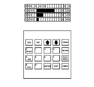
The most dominant input frequencies, up to three, received from the EL-38792-A Electronic
Vibration Analyzer 2 (EVA 2) vibration sensor, are displayed in descending order of amplitude
strength.
The frequency readings are displayed along the left side of the screen, followed to the right by
either a bar graph or the suspected source of the vibration – depending upon the mode selected,
then the amplitude reading for each frequency along the right side of the screen. The top row of
the screen indicates the units of measure being displayed for the frequencies along the left side
and for the amplitudes along the right side. The top row also indicates the vibration sensor input
port which was selected on the keypad (A or B) and which mode was selected: averaging or non-
averaging (instantaneous).
The frequency(ies) can be displayed in either revolutions per minute (RPM) or revolutions per
second; Hertz (Hz). The selected display type (RPM or Hz) will be indicated at the left side of the
screen, above the frequency readings.
When the AUTO MODE function is not in use, a bar graph is displayed next to each frequency to
provide a quick visual indication of the relative amplitude strength.
When the AUTO MODE function is being used, the suspected source of the vibration is displayed
next to each frequency to provide support to the diagnostic process.
The actual amplitude strength of each frequency is displayed at the right side of the screen and
shown in G’s-of-acceleration force.