Front Lower Control Arm Replacement (2WD)
Special Tools CH-43631 Ball Joint Separator Equivalent regional tools: Special Tools Removal Procedure
- Remove the front tire and wheel assembly. Tire and Wheel Removal and Installation
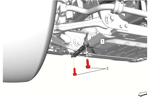
- Front Lower Control Arm Bracket Bolt (2) » Remove [2x]
- Front Lower Control Arm Brace (1) » Remove
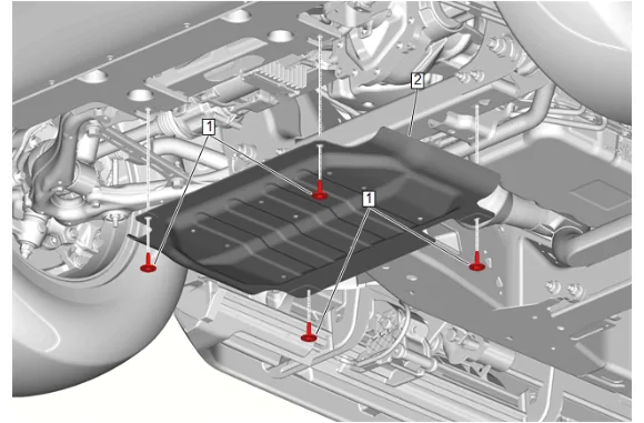
- {Without RC1} Remove the underbody skid shield: 4.1. Underbody Skid Shield Bolt (1) » Remove [4x] 4.2. Underbody Skid Shield (2) » Remove
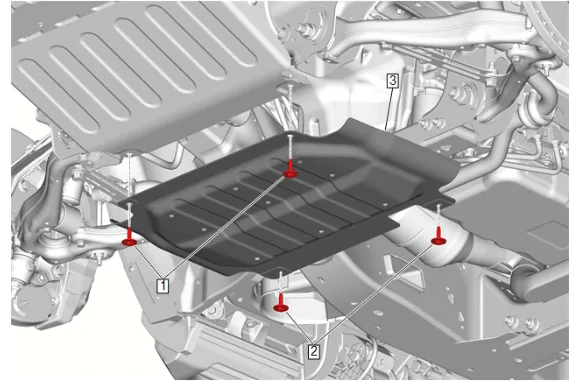
- {With RC1} Remove the underbody skid shield: 5.1. Underbody Skid Shield Bolt (1) » Remove [2x] 5.2. Underbody Splash Shield Bolt (2) » Remove [2x] 5.3. Underbody Skid Shield (3) » Remove
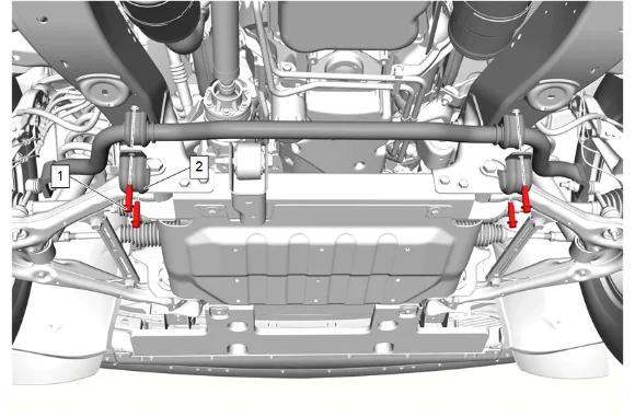
- Front Stabilizer Shaft Bolt (1) » Remove [4x]
- Front Stabilizer Shaft Clamp (2) » Remove [2x]
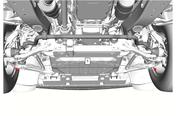
- Front Stabilizer Shaft Link Nut - Lower (1) @ Front Stabilizer Shaft » Remove [2x]
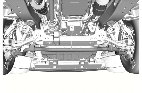
- Remove the front stabilizer shaft (1) and front stabilizer shaft links together.
- Support the steering knuckle with a suitable jack stand.
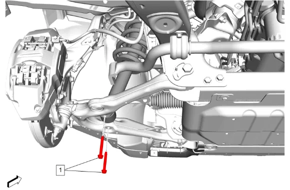
- Front Shock Absorber Bolt (1) » Remove [2x]
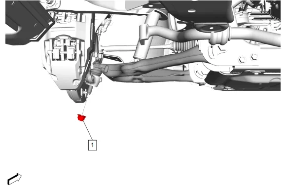
- Front Lower Control Arm Ball Stud Nut (1) » Remove
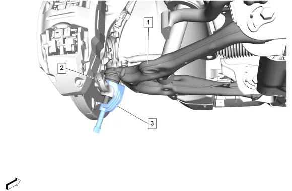
- Front Lower Control Arm (1) @ Steering Knuckle (2) » Release — use CH-43631 Ball Joint Separator (3)
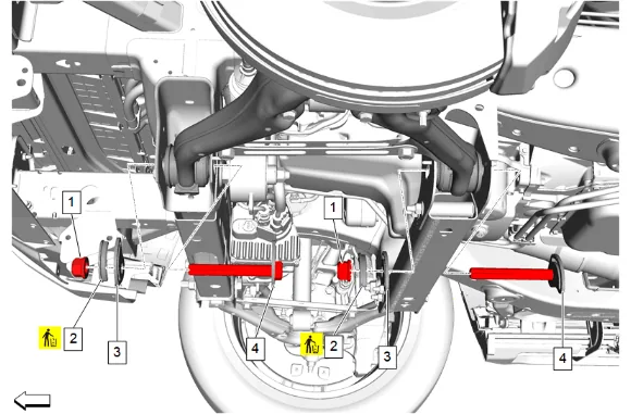
- Mark the relationship of the front lower control arm adjust cams (3) and the front lower control arm adjust bolts (4) to the frame pins using a grease pencil.
- Front Lower Control Arm Nut (1) » Remove [2x]
- If equipped, remove and DISCARD the 2 front lower control arm adjust cam retainers (2).
- Front Lower Control Arm Adjust Cam (3) » Remove [2x]
- Front Lower Control Arm Adjust Bolt (4) » Remove [2x]
-
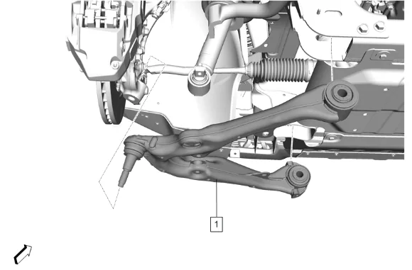
Front Lower Control Arm (1) » Remove Installation Procedure
-
Front Lower Control Arm (1) » Install
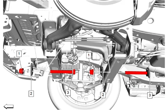
- Front Lower Control Arm Adjust Bolt (3) » Install [2x]
- Front Lower Control Arm Adjust Cam (2) » Install [2x]
- Align the marks made on the front lower control arm adjust cams (2) and the front lower control arm adjust bolts (3) to the frame pins.
- Front Lower Control Arm Nut (1) » Install and hand tighten [2x]
- Support the steering knuckle with a suitable jack stand.
-
Front Lower Control Arm Ball Stud Nut (1) » Install and tighten — Fastener Specifications
-
Front Shock Absorber Bolt (1) » Install [2x] — Fastener Specifications
-
Remove the jack stand supporting the steering knuckle.
-
Install the front stabilizer shaft links and the front stabilizer shaft (1).
-
Front Stabilizer Shaft Link Nut - Lower (1) @ Front Stabilizer Shaft » Install and tighten [2x] — Fastener Specifications
-
Front Stabilizer Shaft Clamp (2) » Install [2x]
-
If NEW threaded components are being installed, loosen the adhesive using a metal pick or similar tool before proceeding. If threaded components are reused, prepare the threaded components using the following steps: 13.1. Remove any loose cured adhesive from the external threads of the components using a lint free cloth. 13.2. Thread the cleaned components into the internal mating threads and remove to loosen trapped cured adhesive. 13.3. Apply thread locking adhesive to the external threads of the components. Adhesives, Fluids, Lubricants, and Sealers 13.4. Ensure there are no gaps in the thread locking adhesive once applied to the component.
-
Front Stabilizer Shaft Bolt (1) » Install and tighten [4x] — Fastener Specifications
-
Front Lower Control Arm Brace (1) » Install
-
Front Lower Control Arm Bracket Bolt (2) » Install and tighten [2x] — Fastener Specifications
-
{With RC1} Install the underbody skid shield: 17.1. Underbody Skid Shield (3) » Install 17.2. Underbody Splash Shield Bolt (2) » Install and tighten [2x] — Fastener Specifications 17.3. Underbody Skid Shield Bolt (1) » Install and tighten [2x] — Fastener Specifications
-
{Without RC1} Install the underbody skid shield: 18.1. Underbody Skid Shield (2) » Install 18.2. Underbody Skid Shield Bolt (1) » Install and tighten [4x] — Fastener Specifications
-
Install the front tire and wheel assembly. Tire and Wheel Removal and Installation
-
Measure and adjust the wheel alignment. Front Caster and Camber Adjustment