Probing Electrical Connectors
Special Tools EL-35616 Terminal Test Probe Kit For equivalent regional tools, refer to Special Tools. Danger: This procedure should not be performed on high voltage circuits. Performing this procedure on high voltage circuits may result in serious injury or death.
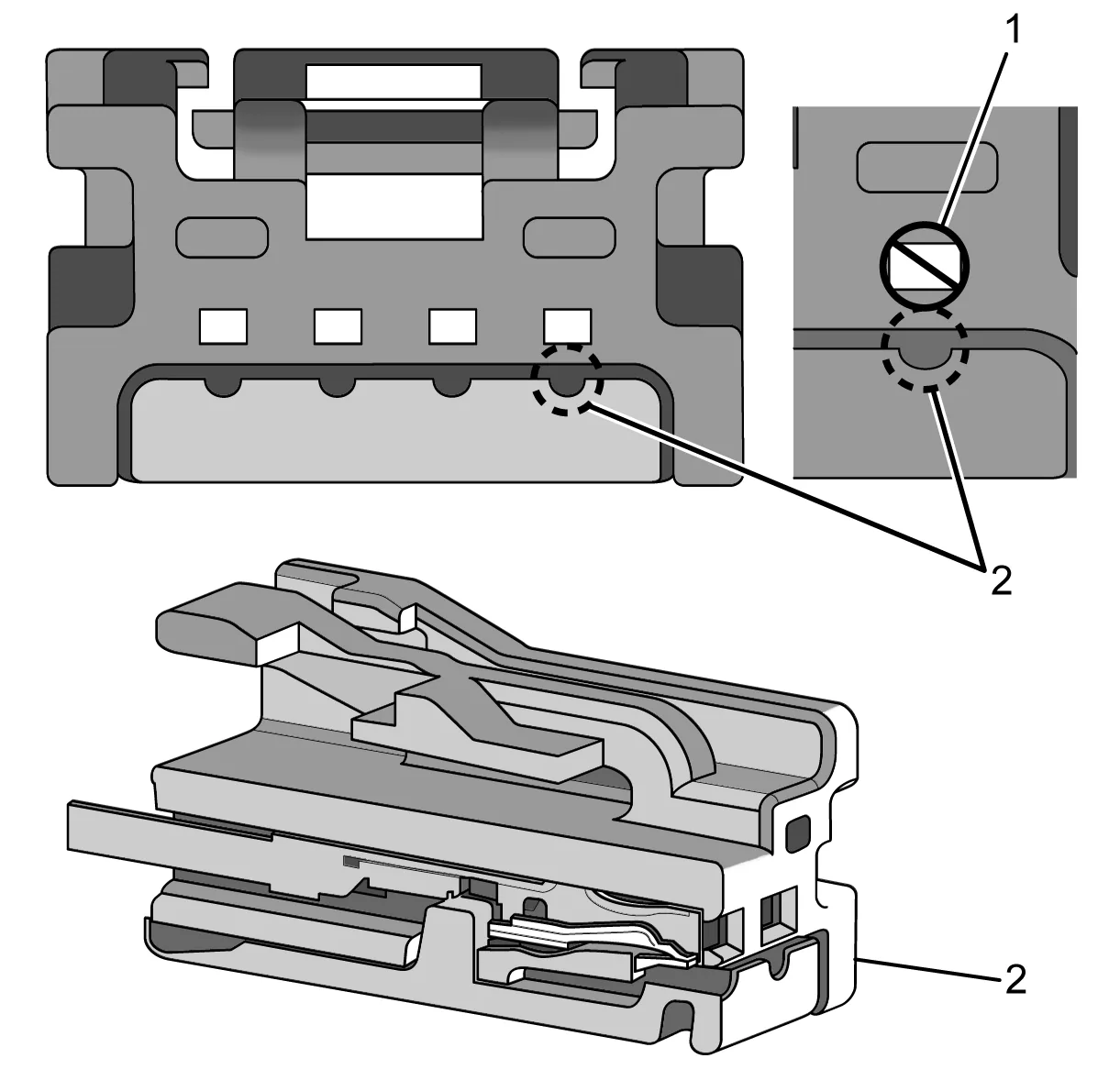
- Disconnect the electrical connector.
- Insert the appropriate test adapter straight into the terminal on the mating side (front) of the connector. Refer to the appropriate Connector End View to determine the correct test adapter for front probing terminals. Back probe
- Disconnect the electrical connector that will be back probed. This allows increased maneuverability of the connector when inserting the back probe test lead J-35616-220 and will help reduce the opportunity for damage.
- Insert the back probe test lead into the back of the terminal, between the terminal and the connector body.
- Measure the resistance between the back probe test lead and the corresponding terminal on the front of the connector to ensure a good connection was made. If excessive resistance is found, reposition the back probe test lead to ensure good contact between the back probe test lead and the terminal.
- Connect the electrical connector with the back probe test lead installed and continue diagnosis.