Cooling System Description and Operation (LM2)
Engine Coolant Indicators Engine Hot - AC Off The instrument panel cluster (IPC) displays Engine Hot - AC Off message when the IPC receives a message from the powertrain control module (PCM) requesting illumination of this driver warning when the temperature reaches 119°C (246°F). Engine Hot - Idle Engine The IPC Engine Hot - Idle Engine when the IPC receives a message from the PCM requesting illumination of this driver warning when the temperature reaches 130°C (266°F). Engine Hot - Turn Engine Off The IPC displays Engine Hot - Turn Engine Off message when the IPC detects a reduced engine power condition from the PCM. The IPC receives a message from the PCM requesting illumination when the engine temperature reaches 133°C (271°F). Cooling System Active Thermal Management This vehicle uses an improved cooling system design, which makes use of an Active Thermal Management (ATM) strategy. The predominant goal of the ATM strategy is to prioritize fuel economy by maintaining an ideal engine operating temperature during all engine speeds and operating conditions, while still meeting customer expectations for vehicle performance and reducing vehicle emissions. The key features of ATM include: Mechanical water pump, which provides constant coolant flow to the engine cylinder block, cylinder head, and the engine coolant flow control valve. Engine coolant flow control valve, which contains two internal control valves, the main rotary control valve and the block control valve. This combination of the main rotary control valve and the block control valve is critical to achieving optimal combustion chamber temperatures as quickly as possible during engine warm up. This independent control is known as split cooling. The engine coolant flow control valve eliminates the need for a conventional cooling system thermostat. The block control valve receives coolant flow from the cylinder block and controls the cylinder block temperature. It can be activated at any point during vehicle operation and when opened flows coolant into the main rotary control valve. Main Rotary Control Valve
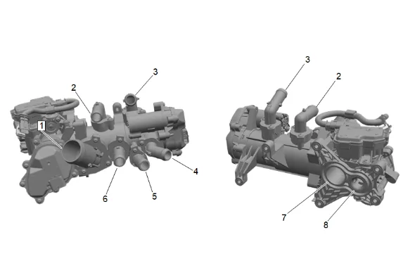
(1) Out to radiator (2) Out to EGR (3) In from EGR (4) Feed from water pump (5) Outlet to engine oil cooler and automatic transmission fluid cooling exchanger (6) Return to water pump (7) Inlet from cylinder head (8) Inlet from engine block The main rotary control valve receives coolant flow via the cylinder head and the cylinder block control valve as well as directly from the mechanical water pump. The main rotary control valve controls the flow of coolant through the radiator, engine oil heater, engine oil pump via a passage through the lower crankcase extension, transmission oil heater and oil cooler, turbocharger, low pressure EGR cooler, high pressure EGR valve (to keep electronics cooled), exhaust throttle valve (to keep electronics cooled), cabin heater core, and cylinder head by-pass circuit. The Engine control module (ECM), which controls the complete ATM system using feedback from numerous sensors. Various temperature and position sensors provide data back to the engine control module. Engine Block Coolant Temperature Sensor Engine Cylinder Head Coolant Temperature Sensor Engine Inlet Coolant Temperature Sensor Engine Outlet Coolant Temperature Sensor Engine Oil Temperature Sensor 1 and 2 Transmission Oil Temperature Sensor Radiator Outlet Coolant Temperature Sensor Engine Coolant Flow Control Valve Position Sensors (internal) Engine Oil Heater The engine oil heater is a heat exchanger and is attached to the side of the engine and exchanges heat between the engine oil and engine coolant. Automatic Transmission Fluid Heater The automatic transmission fluid cooling exchanger is a heat exchanger that is attached to the front of the transmission and exchanges heat between the transmission oil and engine coolant. The automatic transmission fluid cooling exchanger can flow no coolant, provide hot coolant for transmission oil heating (during engine warm-up) or provide cooled coolant for transmission oil cooling (under high thermal loads). Transmission Fluid Auxiliary Cooler The transmission fluid auxiliary cooler is a an air to oil heat exchanger mounted in front of the air conditioning condenser. It is connected by hoses/pipes in series with the transmission mounted heat exchanger. The transmission fluid auxiliary cooler is used if additional fluid cooling is needed. The flow to this cooler is controlled by a thermal by-pass valve. Auxiliary Coolant Pump There is an auxiliary coolant pump receives coolant from the cabin heater core and the cylinder head by-pass circuit. This pump is used to assist with moving coolant back to the engine mechanical water pump. This is used during Stop/Start operation to improve heater performance. ATM still uses many of the conventional cooling system features, including: Coolant Coolant Hoses Radiator Radiator Bypass Route Radiator Surge Tank Surge Tank Pressure Cap Engine Coolant Indicators Air Baffles/Guides and Seals Cabin Heater Core Route Coolant The engine coolant is a solution made up of a 50 - 50 mixture of DEX-COOL® and suitable drinking water. The coolant solution transfers heat between the components of the engine heating/cooling system. Radiator The radiator is a heat exchanger. It consists of a core and two end tanks. The aluminum core is a tube and fin crossflow design that extends from the inlet tank to the outlet tank. Fins are placed around the outside of the tubes to improve heat transfer to the atmosphere. The inlet and outlet tanks are a molded high temperature nylon reinforced plastic material. A high temperature rubber gasket seals the tank flange edge to the aluminum core. The tanks are clamped to the core with clinch tabs. The tabs are part of the aluminum header at each end of the core. The radiator also has a drain cock located in the bottom of the left or right hand tank. The drain cock unit includes the drain cock and drain cock seal. Heat is removed from the coolant as the coolant passes through the radiator. The fins on the core transfer heat from the coolant passing through the tubes. Air passing between the fins absorbs the heat and cools the coolant. Radiator Surge Tank The radiator surge tank is a plastic tank with a pressure cap mounted to it. The tank is mounted at a point higher than all other coolant passages. The surge tank provides an air space in the cooling system. The air space allows the coolant to expand and contract. The surge tank also provides a coolant fill point and a central air bleed location. During vehicle use, the coolant heats and expands. The coolant that is displaced by this expansion flows into the surge tank. As the coolant circulates, air is allowed to exit. This is an advantage to the cooling system. Coolant without air bubbles absorbs heat much better than coolant with air bubbles. Radiator Surge Tank Cap The radiator surge tank cap is a pressure cap that seals and pressurizes the cooling system. It contains a blow off or pressure valve and a vacuum or atmospheric valve. The pressure valve is held against its seat by a spring and protects the radiator by relieving pressure if it exceeds 20 psi. The vacuum valve is held against its seat by a spring, which permits opening of the valve to relieve vacuum created in the cooling system as it cools off. The vacuum, if not relieved, could cause the radiator hoses to collapse. The pressure cap allows pressure in the cooling system to build up. As the pressure builds, the boiling point of the coolant goes up as well. Therefore, the coolant can be safely run at a temperature higher than the boiling point of the coolant at atmospheric pressure. The hotter the coolant is, the faster the heat moves from the radiator to the cooler passing air. However, if the pressure exceeds the strength of the spring, the pressure valve rises so that the excess pressure can escape. When the engine cools down, the temperature of the coolant drops and a vacuum is created in the cooling system. This vacuum causes the vacuum valve to open, allowing outside air into the cooling system. This equalizes the pressure in the cooling system with atmospheric pressure, thus preventing the radiator hoses from collapsing. Air Baffles/Guides and Seals The cooling system uses deflectors, air baffles/guides and air seals to increase cooling system capability. Deflectors are installed under the vehicle to redirect airflow beneath the vehicle and through the radiator to increase engine cooling. Air baffles/guides are also used to direct airflow through the radiator and increase cooling capability. Air seals prevent air from bypassing the radiator and air conditioning condenser, and prevent recirculation of hot air for better hot weather cooling and air conditioning condenser performance. Coolant Heater (If Equipped) The optional coolant heater (RPO K05) operates using 110 V AC external power and is designed to warm the coolant in the engine block area for improved starting in very cold weather. The coolant heater also helps reduce fuel consumption when a cold engine is warming up. The unit is equipped with a detachable AC power cord. A weather shield on the cord is provided to protect the plug when not in use. Cooling Cycle Coolant flows from the mechanical water pump outlet and into the engine cylinder block and cylinder head. The mechanical water pump also provides cooled coolant flow from the radiator directly to the engine coolant flow control valve. Input from various temperature and position sensors is used by the ECM to direct the flow of coolant from the engine coolant flow control valve to either heat or cool as necessary components such as engine cylinder block, cylinder head, turbocharger, low pressure EGR cooler, high pressure EGR valve electronics, exhaust throttle valve electronics, engine oil heat exchanger, transmission oil heater/cooler circuit, and cabin heater core. A de-gas circuit is incorporated into the engine cylinder block and head that moves any trapped air bubbles to the surge tank. Secondary Low Temperature Coolant Loop This vehicle also utilizes a secondary coolant loop which circulates coolant to the Water Charge Air Cooler (WCAC), fuel cooler, and the Diesel Exhaust Fluid (DEF) injector via an auxiliary low temperature radiator and chassis mounted electric coolant pump. Coolant flows from the low temperature auxiliary electric coolant pump to the low temperature radiator and then to the fuel cooler and DEF injector prior to entering the WCAC. Coolant exiting the WCAC flows to the low temperature surge tank and the then back to the low temperature auxiliary electric coolant pump. There is a coolant temperature sensor located near the inlet to the WCAC. The key features of the Secondary Low Temperature Coolant Loop include: Low Temperature Auxiliary Coolant Pump This pump provides coolant flow from the low temperature surge tank through the low temperature radiator and on to the fuel cooler, DEF injector and WCAC before returning to the low temperature surge tank. Low Temperature Radiator The radiator is a heat exchanger. It consists of a core and two end tanks. The aluminum core is a tube and fin crossflow design that extends from the inlet tank to the outlet tank. Fins are placed around the outside of these tubes to improve heat transfer to the atmosphere. The inlet and outlet tanks are a molded high temperature nylon reinforced plastic material. A high temperature rubber gasket seals the tank flange edge to the aluminum core. The tanks are clamped to the core with clinch tabs. The tabs are part of the aluminum header at each end of the core. Water Charge Air Cooler The WCAC is a heat exchanger the uses coolant flowing through tubes to cool the air passing outside of those tubes. The air is cooled in the WCAC after exiting the turbocharger before entering the intake manifold. Coolant Temperature Sensor The secondary low temperature cooling loop utilizes a coolant temperature sensor located near the inlet to the WCAC to monitor coolant temperature. This temperature signal is utilized by the ECM to control the low temperature auxiliary coolant pump. Charge Air Cooler Surge Tank The radiator surge tank is a plastic tank with a pressure cap mounted to it. The tank is mounted at a point higher than all other coolant passages. The surge tank provides an air space in the cooling system. The air space allows the coolant to expand and contract. The surge tank also provides a coolant fill point and a central air bleed location. During vehicle use, the coolant heats and expands. The coolant that is displaced by this expansion flows into the surge tank. As the coolant circulates, air is allowed to exit. This is an advantage to the cooling system. Coolant without air bubbles absorbs heat much better than coolant with air bubbles. Charge Air Cooler Surge Tank Cap The charge air cooler surge tank cap is a pressure cap that seals and pressurizes the low temp cooling system. It contains a blow off or pressure valve and a vacuum or atmospheric valve. The pressure valve is held against its seat by a spring and protects the radiator by relieving pressure if it exceeds 5 psi. The vacuum valve is held against its seat by a spring, which permits opening of the valve to relieve vacuum created in the low temp cooling system as it cools off. The vacuum, if not relieved, could cause the radiator hoses to collapse. The pressure cap allows pressure in the cooling system to build up. As the pressure builds, the boiling point of the coolant goes up as well. Therefore, the coolant can be safely run at a temperature higher than the boiling point of the coolant at atmospheric pressure. The hotter the coolant is, the faster the heat moves from the radiator to the cooler passing air. However, if the pressure exceeds the strength of the spring, the pressure valve rises so that the excess pressure can escape. When the engine cools down, the temperature of the coolant drops and a vacuum is created in the cooling system. This vacuum causes the vacuum valve to open, allowing outside air into the cooling system. This equalizes the pressure in the cooling system with atmospheric pressure, thus preventing the radiator hoses from collapsing.