Reverse (Hydraulic Circuits)
When the gear selector is moved to the Reverse (R) position (from the Park position) the shift solenoid D and F are commanded ON, and the following changes occur in the transmission’s hydraulic and electrical systems: Fluid Pressure Directed in Preparation for a Power Loss Situation Default Disable Solenoid The default disable solenoid is energized on allowing ON/OFF SIGNAL (19) fluid to enter the FEED LIMIT – LOW (15) fluid circuit. FEED LIMIT – LOW (15) fluid is directed to the default disable valve, feed limit valve – low, ball check valve # 1 and ball check valve # 2. The default solenoid controls the default disable valve, which controls the system to pressurize clutches through their exhaust ports to hold either gear in a power loss situation. Default disable solenoid has to be on to keep out of default. Default in Reverse gives Reverse, while default in Drive gives 7th gear initially. The vehicle will restart in 2nd gear after a key cycle or a Drive-Reverse-Drive state change, as determined by the Drive Select valve’s latch state. Drive and reverse oils are controlled by a manual shaft. There needs to be a minimum of 450 kpa line pressure to result in a gear under default. This is due to the spring pressure of the default disable valve. Feed Limit Valves The boost ball system uses two additional pressure circuits called FEED LIMIT - LOW (15) and FEED LIMIT – HIGH (16). These circuits control the pressure at which the circuit boosts to line pressure. The FEED LIMIT - LOW (15) circuit controls the boost balls for clutches 1-2-3-4-5-6 R and 1-2-8-9-10 R, while the FEED LIMIT – HIGH (16) circuit is used for clutches 2-3-4-5-7-9- 10 and 1-2-3-4-6-7-8-10 R. The following is the range on feed limit pressures at which boost can happen. FEED LIMIT - LOW (15) boost range is a minimum of 660 to a maximum of 825 kpa. FEED LIMIT – HIGH (16) boost range is a minimum of 1000 to a maximum of 1252 kpa. ETRS Valve The default disable solenoid is pressurized and moves the ETRS Mode Valve, whose position is read by a switch. This allows line pressure to feed Out of Park oil which shifts over the Park Servo valve, and its position is recorded with two position switches. Park Servo Valve The Park Servo valve is held in the out of park position by the Park Inhibit Solenoid. The park inhibit solenoid is only designed to hold the trans out of park against the park servo spring, so any pressure at the return to park end of the servo can cause the park inhibit solenoid to be overcome. 1-2-3-4-6-7-8-10 Reverse Clutch Applies 1-2-3-4-6-7-8-10 Reverse Clutch Regulator Valve Shift solenoid valve D is energized and applying pressure against the 1-2-3-4-6-7-8-10 reverse clutch regulator valve allowing LINE (2) fluid to enter the 1234678-10R CLUTCH (30) fluid circuit. 1234678-10R CLUTCH (30) fluid is also directed through orifice #21 into the 1234678-10R CLUTCH FEEDBACK (31) fluid passage to the 1-2-3-4-6-7-8-10 reverse clutch regulator valve. 1-2-3-4-6-7-8-10 Reverse Clutch Assembly 1234678-10R CLUTCH (30) fluid is directed through orifice # 24 into the 1-2-3-4-6-7-8-10 reverse clutch assembly. 1234678- 10R CLUTCH (30) fluid moves the piston against spring force to apply holding of the 1-2-3-4-6-7-8-10 reverse clutch plates. 4-5-6-7-8-9-10 Reverse Clutch Applies 4-5-6-7-8-9-10 Reverse Clutch Regulator Valve Shift solenoid valve F is energized and applying pressure against the 4-5-6-7-8-9-10 reverse clutch regulator valve allowing 456789-10R (20) fluid to enter the 456789-10R CLUTCH (36) fluid circuit. 456789-10R CLUTCH (36) fluid is directed to the 4- 5-6-7-8-9-10 reverse clutch assembly. 456789-10R CLUTCH (36) fluid is also directed through orifice #31 into the 456789-10R CLUTCH FEEDBACK (37) fluid passage to the #4 ball check valve which seats against the FEED LIMIT – HIGH (16) fluid passage. 4-5-6-7-8-9-10 Reverse Clutch Assembly 456789-10R CLUTCH (36) fluid is directed through orifice # 34 into the 4-5-6-7-8-9-10 reverse clutch assembly. 456789-10R CLUTCH (36) fluid moves the piston against spring force to apply holding of the 4-5-6-7-8-9-10 reverse clutch plates. Reverse
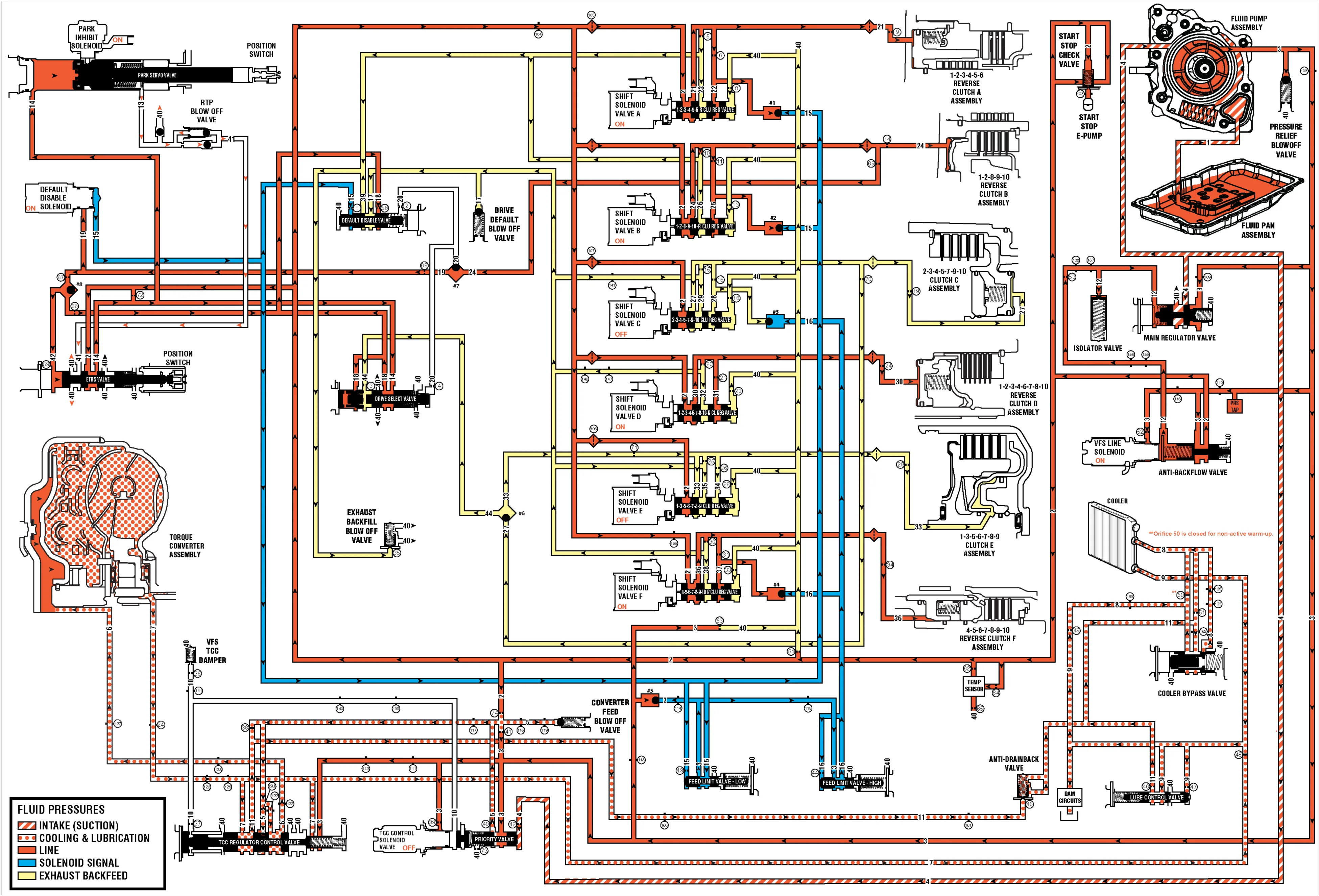
(1) Suction (2) Line (3) Pump Out (4) Decrease (5) Converter Feed (6) TCC Release (7) TCC Apply (8) Cooler Feed (9) Lube (10) VFS-TCC (11) Converter Return (12) VFS Line (13) Park On (14) Park Off (15) Feed Limit – Low (16) Feed Limit – High (17) Drive Default (18) Drive Latch (19) ON/OFF Signal (20) On/Off 1289-10 Reverse Clutch (21) 123456 Reverse Clutch (22) 123456 Reverse Clutch Feedback (23) 123456 Reverse Clutch Exhaust (24) 1289-10 Reverse Clutch (25) 1289-10 Reverse Clutch Feedback (26) 1289-10 Reverse Clutch Exhaust (27) 234579-10 Clutch (28) 234579-10 Clutch Feedback (29) 234579-10 Clutch Exhaust (30) 1234678-10 Reverse Clutch (31) 1234678-10 Reverse Clutch Feedback (32) 1234678-10 Reverse Clutch Exhaust (33) 1356789 Clutch (34) 1356789 Clutch Feedback (35) 1356789 Clutch Exhaust (36) 456789-10 Reverse Clutch (37) 456789-10 Reverse Clutch Feedback (38) 456789-10 Reverse Clutch Exhaust (39) Exhaust Backfill (40) Exhaust (41) Return to Park (42) On/Off Drive Latch (44) 234579-10/1356789 CLUTCH