Engine Mount Replacement - Right Side
Single Use Fasteners and Components Air Conditioning Compressor and Condenser Hose Seal [2x] Air Conditioning Evaporator Thermal Expansion Valve Seal - Small Air Conditioning Evaporator Thermal Expansion Valve Seal - Large Catalytic Converter Clamp Catalytic Converter Gasket Emission Reduction Fluid Injector Clamp Engine Mount Engine Side Bolt [2x] Engine Mount Frame Side Bolt [3x] Exhaust Gas Recirculation Cooler Inlet Pipe Gasket - Lower Exhaust Gas Recirculation Cooler Inlet Pipe Gasket - Upper Exhaust Gas Recirculation Outlet Pipe Gasket Exhaust Gas Recirculation Valve Cooler Gasket Exhaust Gas Recirculation Valve Inlet Gasket Exhaust System Front Gasket [2x] Turbocharger Coolant Feed and Return Pipe Gasket Special Tools Engine Mechanical - 3.0L (LM2) EN-36857 Engine Lift Bracket EN-51768 Engine Support Fixture Adaptor Bolt - M8 Equivalent regional tools: Special Tools
- Recover the refrigerant. Refrigerant Recovery and Recharging
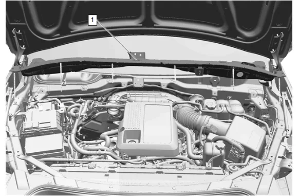
- Plenum Front Panel Outer Reinforcement (1) » Remove — Plenum Front Panel Outer Reinforcement Removal and Installation
- Oil Filler Cap » Remove
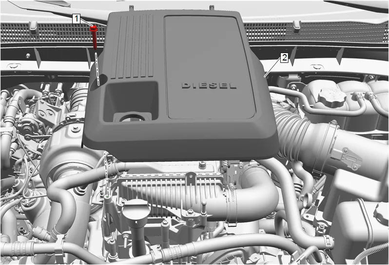
- Intake Manifold Cover Bolt (1) » Remove
- Intake Manifold Cover (2) » Remove
- Install the oil filler cap after removal of the intake manifold cover to prevent debris from falling into the engine.
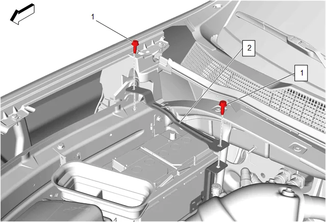
- Battery Hold Down Strap Bolt (1) » Remove [2x]
- Battery Hold Down Strap (2) » Reposition
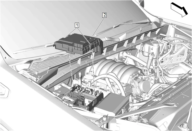
- Retaining Tab (1) » Disengage [2x]
- Front Compartment Fuse Block Cover (2) » Remove
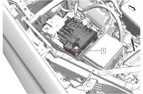
- Battery Positive Post Clamp Nut (1) » Loosen
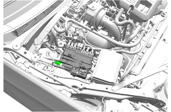
- Electrical Connector (1) » Disconnect
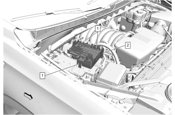
- Retaining Tab (1) » Disengage [3x]
- Battery Distribution Engine Compartment Fuse Block (2) » Reposition
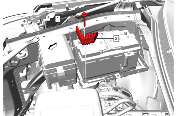
- Battery Hold Down Retainer Bolt (1) » Remove
- Battery Hold Down Retainer (2) » Remove

- Battery (1) » Remove
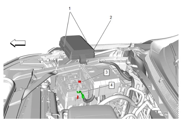
- Retaining Tab (1) » Disengage [2x]
- Engine Wiring Harness Junction Block Cover (2) » Remove
- Battery Positive Cable Nut (3) » Remove
- Starter Solenoid Cable (4) » Remove
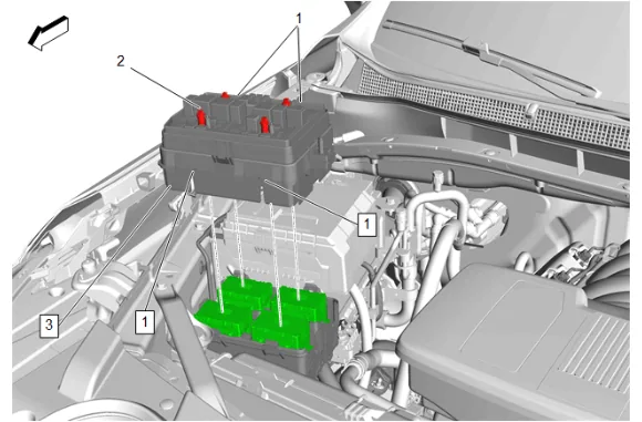
- Engine Wiring Harness Junction Block Bolt (2) » Loosen [4x]
- Retaining Tab (1) » Disengage [4x]
- Engine Wiring Harness Junction Block (3) » Remove
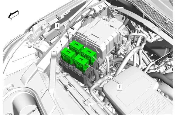
- Electrical Connector (1) » Remove [4x]
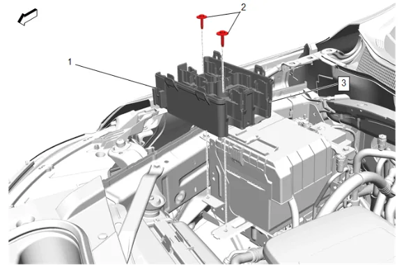
- Engine Wiring Harness Fuse Block Bracket Bolt (2) » Remove [2x]
- Retaining Tab (1) » Disengage
- Engine Wiring Harness Fuse Block Bracket (3) » Remove
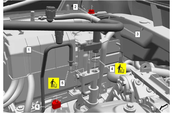
- Air Conditioning Compressor and Condenser Hose Nut (2) @ Air Conditioning Refrigerant Heat Exchanger » Remove
- Air Conditioning Compressor and Condenser Hose (3) @ Air Conditioning Refrigerant Heat Exchanger » Remove
- Air Conditioning Compressor and Condenser Hose Seal (4) » Remove and DISCARD
- Air Conditioning Condenser and Evaporator Hose Clip (6) » Remove
- Air Conditioning Condenser and Evaporator Hose (1) » Remove
- Air Conditioning Compressor and Condenser Hose Seal (5) » Remove and DISCARD
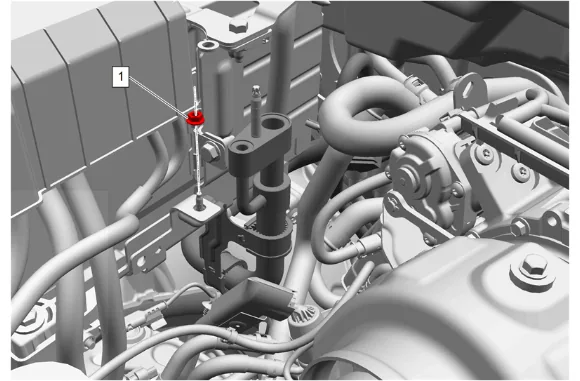
- Air Conditioning Refrigerant Heat Exchanger Nut (1) @ Battery Tray » Remove
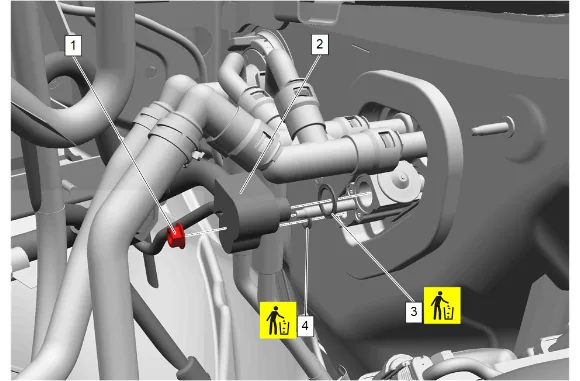
- Air Conditioning Evaporator Thermal Expansion Valve Hose Nut (1) » Remove
- Air Conditioning Refrigerant Heat Exchanger (2) » Remove
- Air Conditioning Evaporator Thermal Expansion Valve Seal - Large (3) » Remove and DISCARD
- Air Conditioning Evaporator Thermal Expansion Valve Seal - Small (4) » Remove and DISCARD
- Remove retainers as needed.
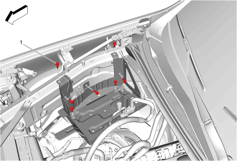
- Battery Tray Bolt (1) » Remove [7x]
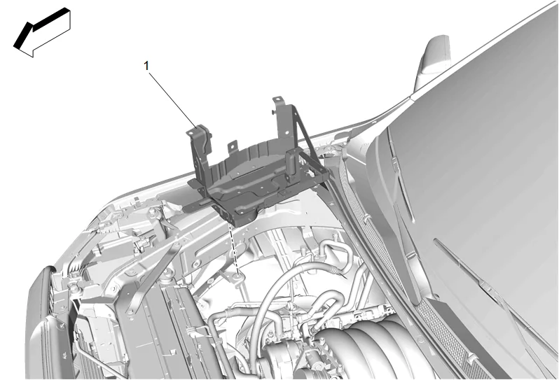
- Battery Tray (1) » Remove
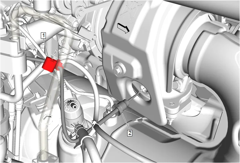
- Exhaust Gas Recirculation Temperature Sensor (2) » Remove and position aside
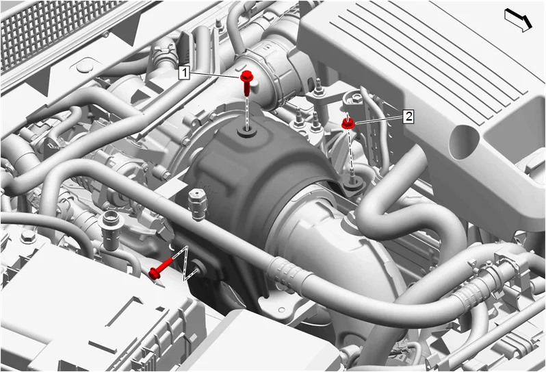
- Turbocharger Heat Shield Bolt (1) » Remove [2x]
- Turbocharger Heat Shield Nut (2) » Remove
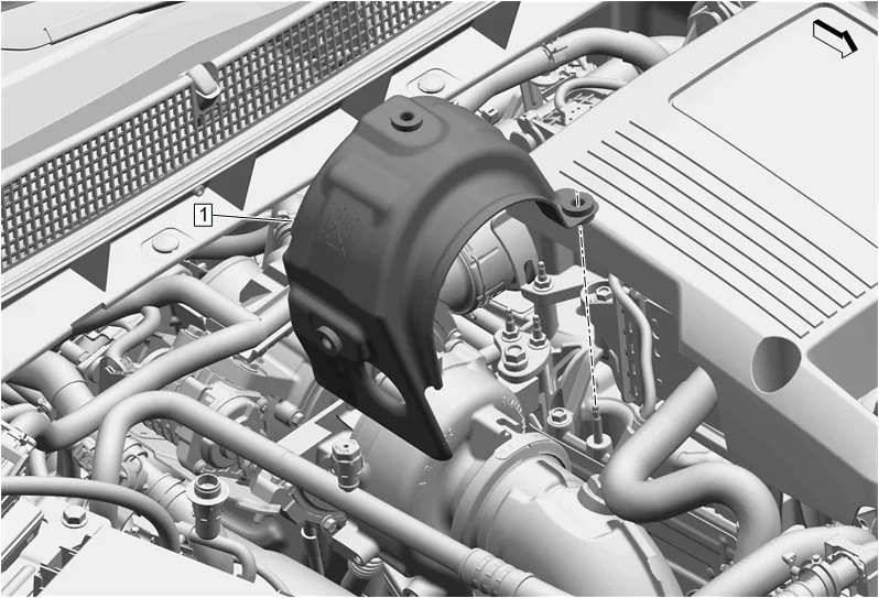
- Turbocharger Heat Shield (1) » Remove
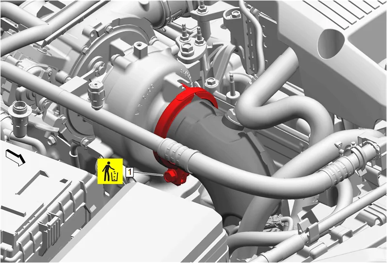
- Catalytic Converter Clamp (1) » Loosen
- Nitrogen Oxides Sensor » Remove and position aside
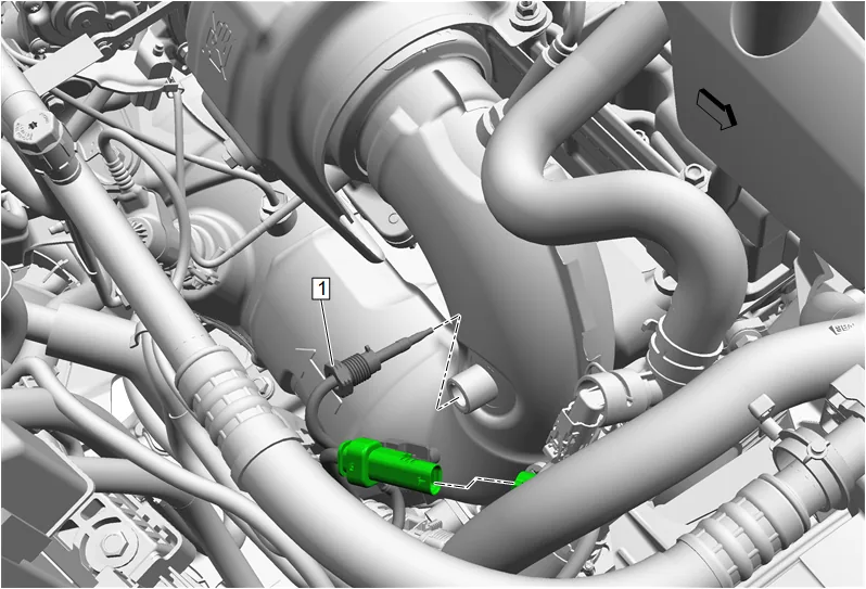
- Exhaust Temperature Sensor - Position 1 (1) » Remove and position aside
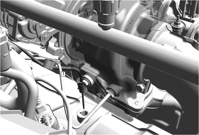
- Exhaust Temperature Sensor - Position 2 (1) » Remove and position aside
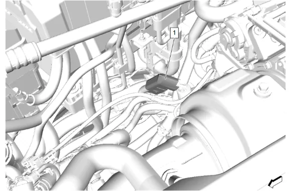
- Emission Reduction Fluid Exhaust Front Pipe Injector Supply Pipe Insulator (1) » Remove
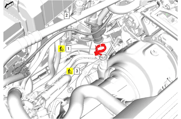
- Emission Reduction Fluid Injector Clamp (1) » Remove and DISCARD
- Reductant Fluid Injector (2) » Reposition
- Exhaust System Front Gasket (3) » Remove and DISCARD
- Clean the exhaust mounting flange and injector mounting surfaces to remove any soot or emission reduction fluid deposits.
- Front Wheelhouse Liner - Right Side (3) » Remove — Front Wheelhouse Liner Replacement
- Drain the cooling system. Cooling System Draining and Filling
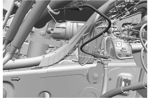
- Exhaust Temperature Sensor - Position 3 (1) » Remove and position aside
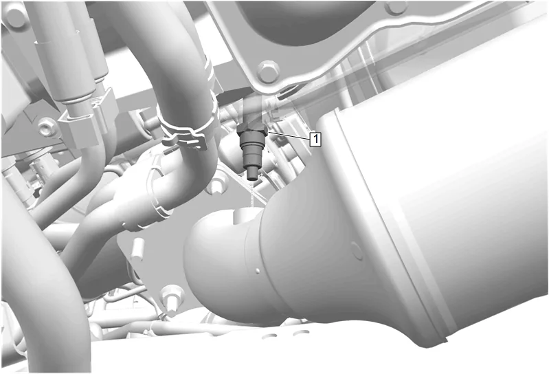
- Using a suitable tool, remove the position 2 nitrogen oxides sensor (1) from the nitrogen oxides catalytic converter.
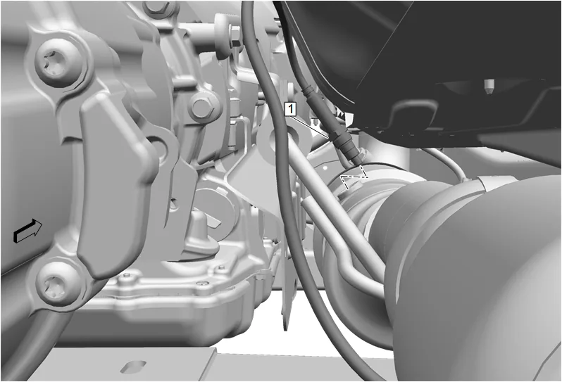
- Using a suitable tool, remove the position 3 nitrogen oxides sensor (1) from the nitrogen oxides catalytic converter.
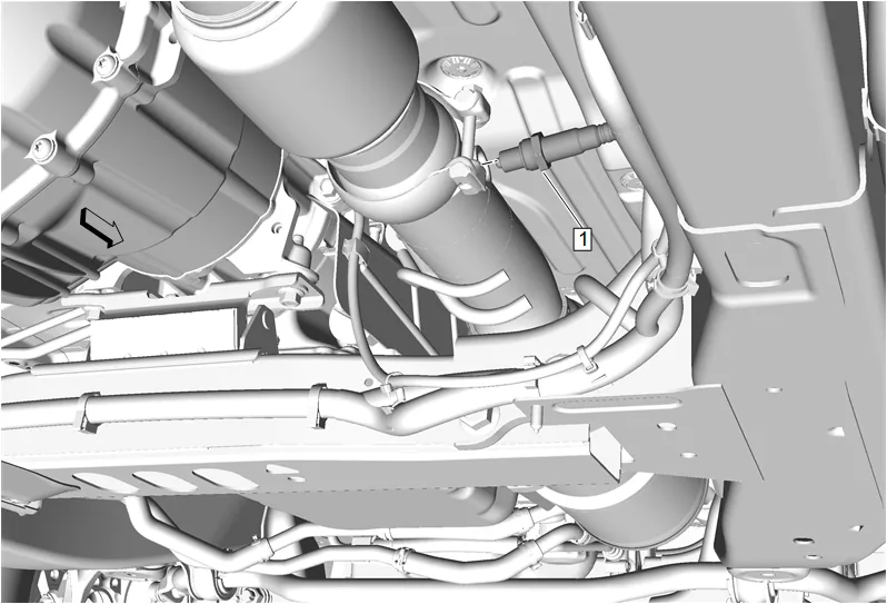
- Using a suitable tool, remove the exhaust particulate sensor (1) from the nitrogen oxides catalytic converter.
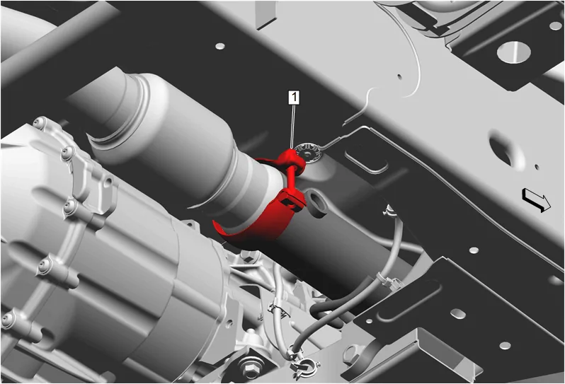
- Exhaust Pipe Clamp (1) » Loosen
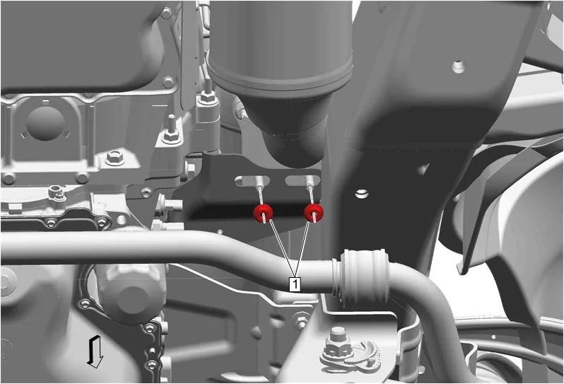
- Exhaust Front Pipe Nut (1) » Remove [2x]
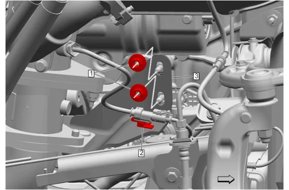
- Catalytic Converter Brace Bracket Nut (1) » Remove [2x]
- Wiring Harness Retainer (2) @ Catalytic Converter Brace Bracket (3) » Remove
- Catalytic Converter Brace Bracket (3) » Remove
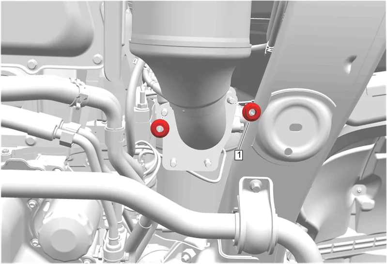
- Exhaust Front Pipe Nut (1) » Remove [2x]
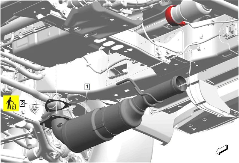
- Nitrogen Oxides Catalytic Converter (1) » Remove
- Exhaust System Front Gasket (2) » Remove and DISCARD
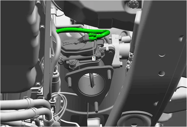
- Electrical Connector (1) @ Exhaust Back Pressure Valve » Disconnect
- Disconnect wiring harness retainers, as required.
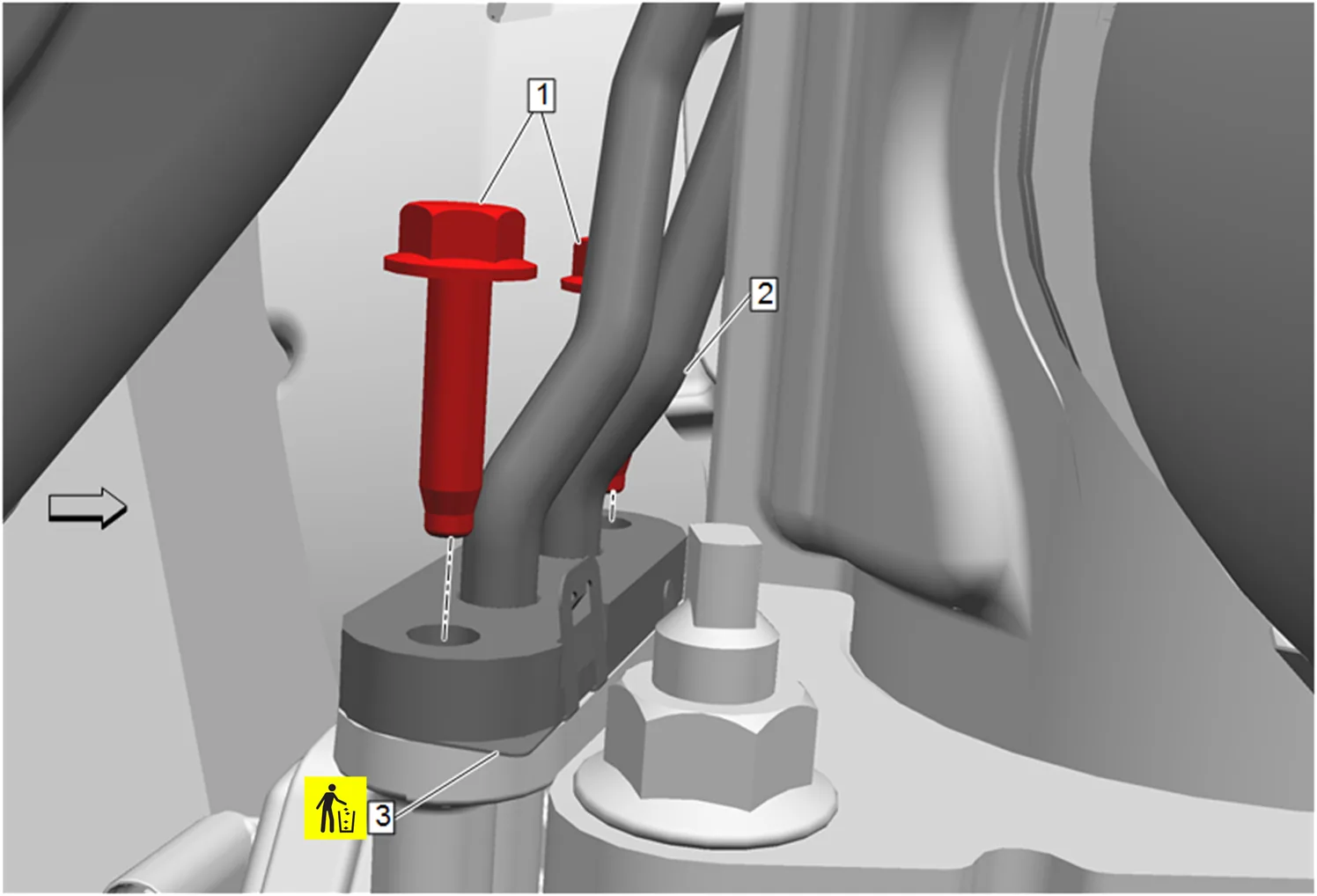
- Exhaust Gas Recirculation Valve Cooling Return Pipe Bolt (1) » Remove [2x]
- Exhaust Gas Recirculation Valve Cooling Return Pipe (2) » Remove
- Turbocharger Coolant Feed and Return Pipe Gasket (3) » Remove and DISCARD
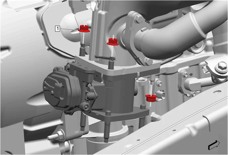
- Catalytic Converter Nut (1) » Remove [3x]
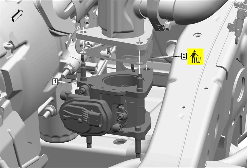
- Exhaust Back Pressure Valve (1) » Remove
- Exhaust Gas Recirculation Valve Inlet Gasket (2) » Remove and DISCARD
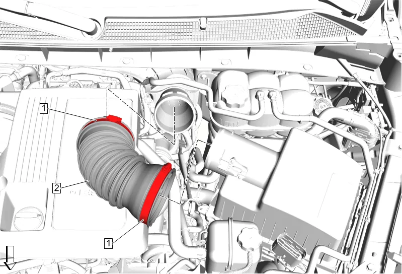
- Air Cleaner Outlet Duct Clamp (1) » Loosen [2x]
- Air Cleaner Outlet Front Duct (2) » Remove
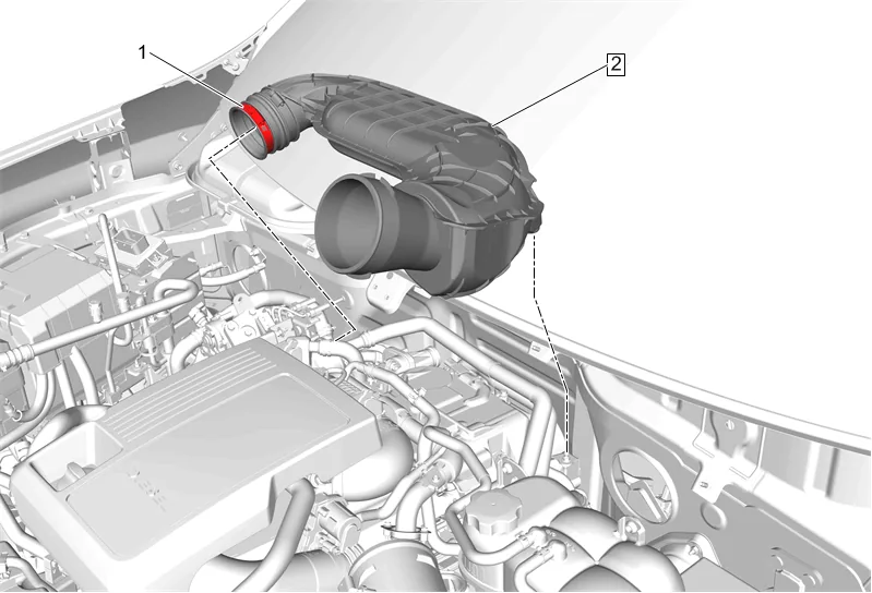
- Air Cleaner Outlet Duct Clamp (1) » Loosen
- Air Cleaner Outlet Duct (2) » Remove
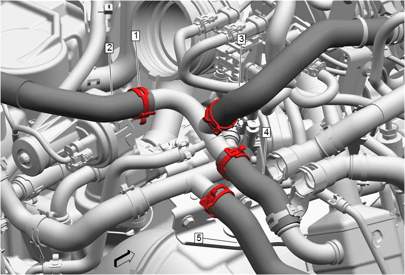
- Hose Clamp (1) » Disengage [4x] — Hose Clamp Replacement Guidelines - Spring Type
- Exhaust Gas Recirculation Coolant Return Pipe (2) @ Exhaust Gas Recirculation Cooler Inlet Pipe » Remove
- Heater Inlet Hose (3) @ Exhaust Gas Recirculation Cooler Inlet Pipe » Remove
- Exhaust Gas Recirculation Cooler Outlet Pipe (4) @ Exhaust Gas Recirculation Cooler Inlet Pipe » Remove
- Exhaust Gas Recirculation Cooler Inlet Pipe (5) @ Exhaust Gas Recirculation Cooler Inlet Pipe » Remove
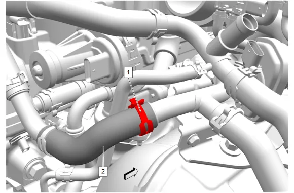
- Hose Clamp (1) » Disengage — Hose Clamp Replacement Guidelines - Spring Type
- Thermostat Bypass Hose (2) @ Exhaust Gas Recirculation Cooler Inlet Pipe » Remove
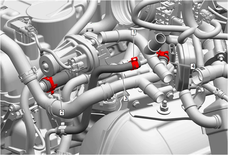
- Hose Clamp (1) » Disengage [2x] — Hose Clamp Replacement Guidelines - Spring Type
- Exhaust Gas Recirculation Valve Cooling Return Hose (3) @ Exhaust Gas Recirculation Cooler Inlet Pipe » Remove
- Turbocharger Coolant Feed and Return Pipe (4) @ Exhaust Gas Recirculation Cooler Inlet Pipe » Remove
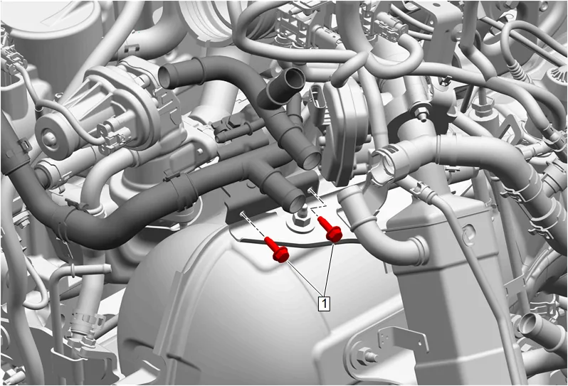
- Exhaust Gas Recirculation Pipe Bracket Bolt (1) » Remove [2x]
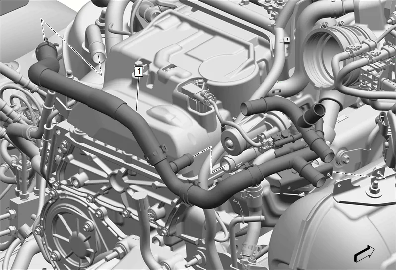
- Exhaust Gas Recirculation Cooler Inlet Pipe (1) » Remove
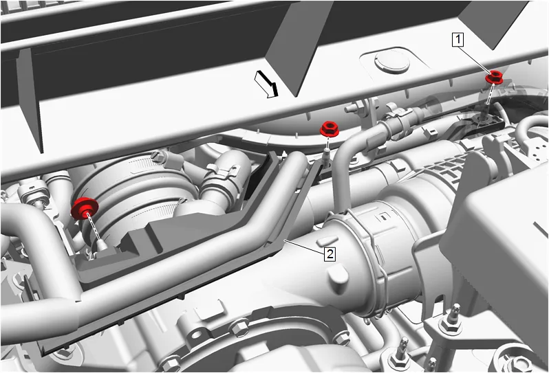
- Remove the 3 rear engine wiring harness channel nuts (1).
- Position the rear engine wiring harness channel (2) out of the way.
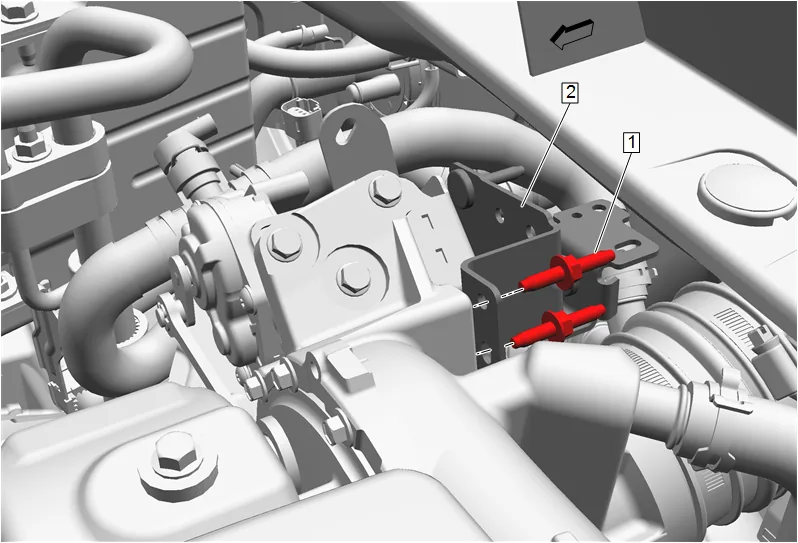
- Remove the 2 exhaust pressure differential sensor bracket studs (1) and reposition the exhaust pressure differential bracket (2).
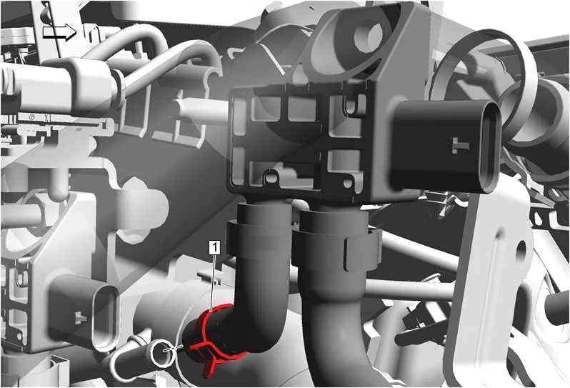
- Disengage the exhaust pressure differential sensor hose clamp (1) and remove the exhaust pressure differential sensor from the exhaust gas recirculation valve hose. Hose Clamp Replacement Guidelines - Spring Type
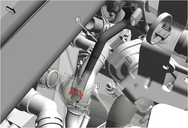
- Disengage the exhaust pressure differential sensor hose clamp (1) and remove the exhaust pressure differential sensor at the exhaust gas recirculation cooler. Hose Clamp Replacement Guidelines - Spring Type
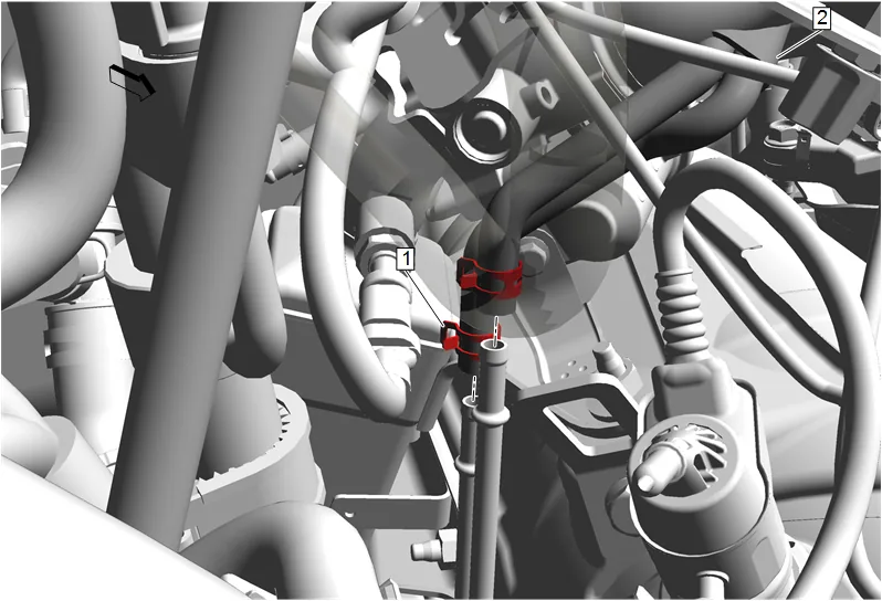
- Disengage the 2 exhaust pressure differential sensor hose clamp (1) and remove the 2 exhaust pressure differential sensor hoses at the exhaust gas recirculation cooler. Hose Clamp Replacement Guidelines - Spring Type
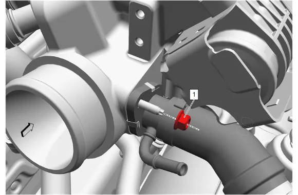
- Exhaust Gas Recirculation Pipe Nut (1) » Remove
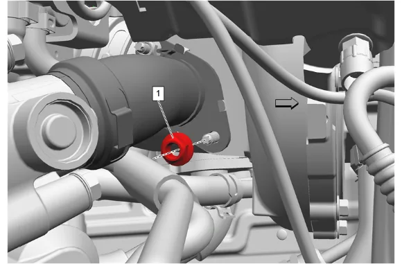
- Exhaust Gas Recirculation Pipe Nut (1) » Remove
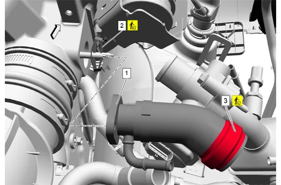
- Exhaust Gas Recirculation Pipe (1) » Reposition
- Exhaust Gas Recirculation Outlet Pipe Gasket (2) » Remove and DISCARD
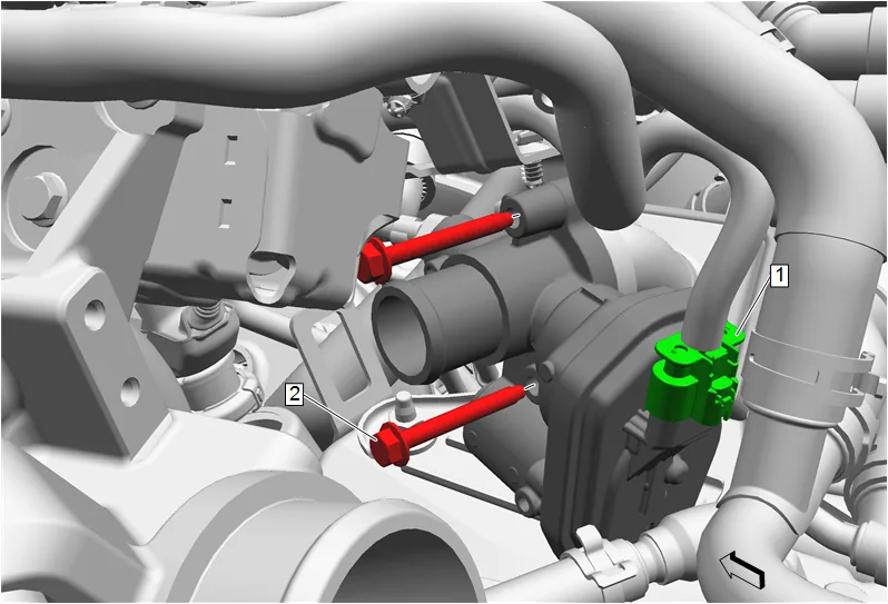
- Disconnect the electrical connector (1).
- Exhaust Gas Recirculation Pipe Bolt (2) » Remove [2x]
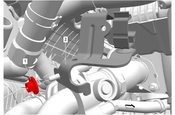
- Exhaust Gas Recirculation Valve Bracket Nut (1) » Remove
- Heater Inlet Hose Bracket (2) » Reposition
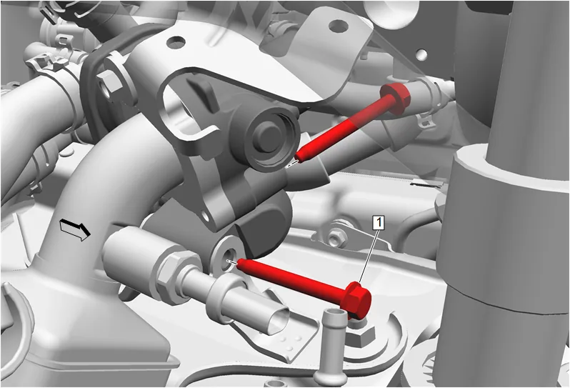
- Exhaust Gas Recirculation Pipe Bolt (1) » Remove [2x]
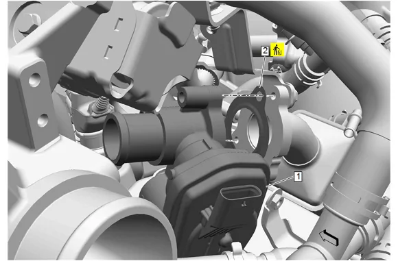
- Remove the exhaust gas recirculation valve (1) with the exhaust gas recirculation valve hose.
- Exhaust Gas Recirculation Valve Cooler Gasket (2) » Remove and DISCARD
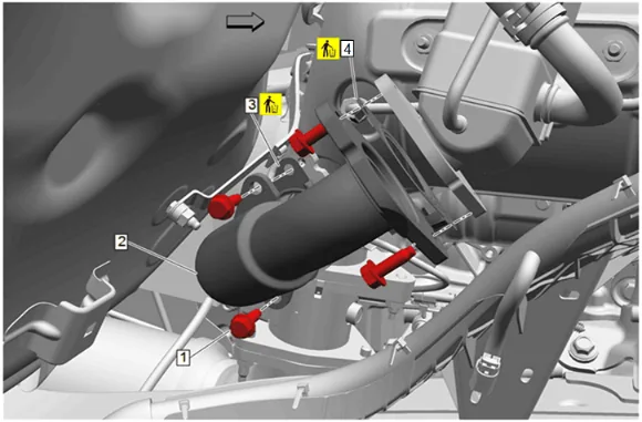
- Exhaust Gas Recirculation Cooler Inlet Pipe Bolt (1) » Remove [4x]
- Exhaust Gas Recirculation Pipe (2) » Remove
- Exhaust Gas Recirculation Cooler Inlet Pipe Gasket - Lower (3) Remove and DISCARD
- Exhaust Gas Recirculation Cooler Inlet Pipe Gasket - Upper (4) Remove and DISCARD
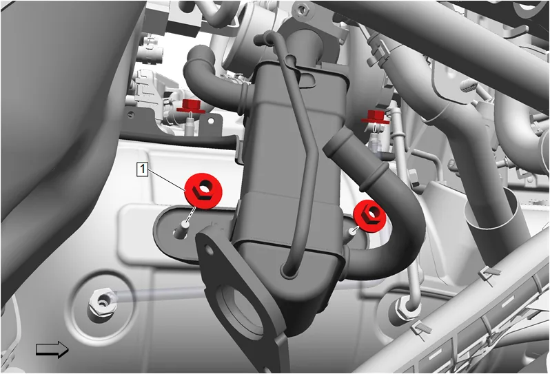
- Disconnect the electrical connector at exhaust gas recirculation cooler.
- Remove the 4 exhaust gas recirculation cooler nuts (1).
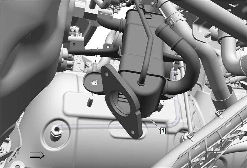
- Remove the exhaust gas recirculation cooler (1).
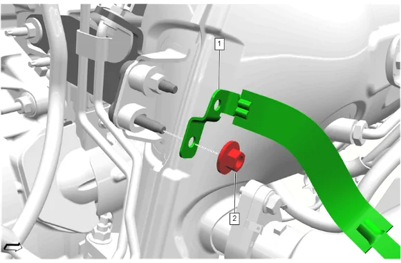
- { If equipped } Catalytic Converter Brace Bracket Nut (2) » Remove
- { If equipped } Battery Negative Cable Extension Cable Strap (1) @ Catalytic Converter Brace Bracket » Remove
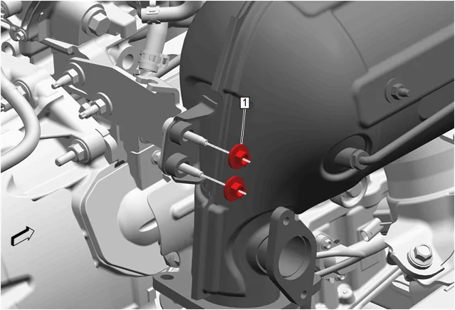
- Catalytic Converter Brace Bracket Nut (1) » Remove [2x]
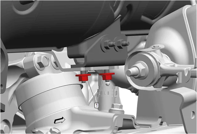
- Catalytic Converter Brace Bracket Nut (1) » Loosen [2x]
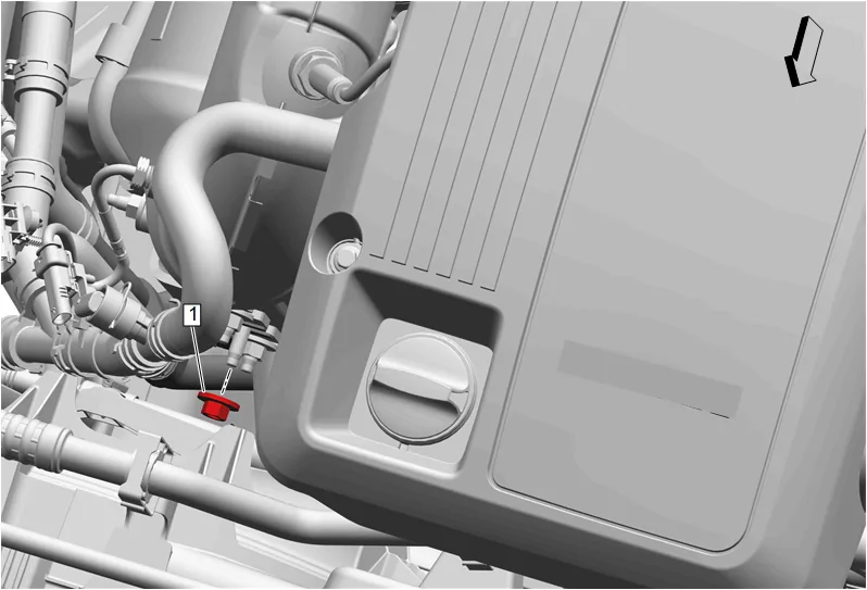
- Fuel Heater Inlet and Outlet Nut (1) » Remove
- Fuel Cooler Coolant Cooler Inlet Hose » Reposition
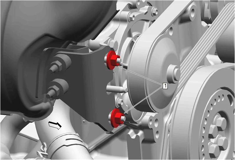
- Catalytic Converter Brace Bracket Nut (1) » Loosen [2x]
- Reposition hoses and wiring harness as needed.
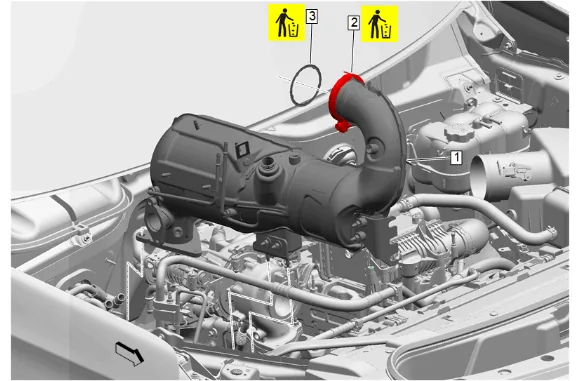
- Nitrogen Oxides Catalytic Converter (1) » Remove
- Catalytic Converter Clamp (2) » Remove and DISCARD
- Catalytic Converter Gasket (3) » Remove and DISCARD
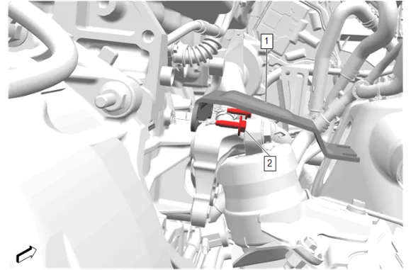
- Catalytic Converter Brace Bracket Bolt (2) » Remove [2x]
- Catalytic Converter Brace Bracket (1) » Remove
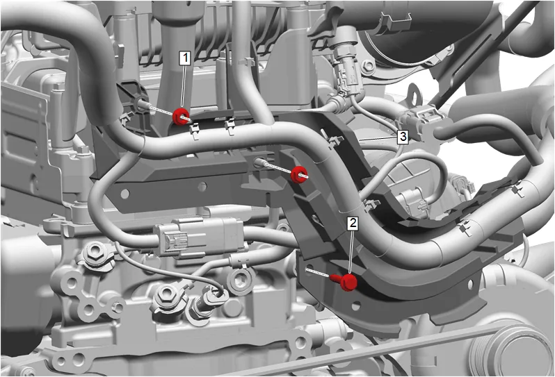
- Engine Wiring Harness Bracket Nut (1) » Remove [2x]
- Engine Wiring Harness Bracket Bolt (2) » Remove
- Reposition the engine wiring harness channel (3) away from the front of the engine.
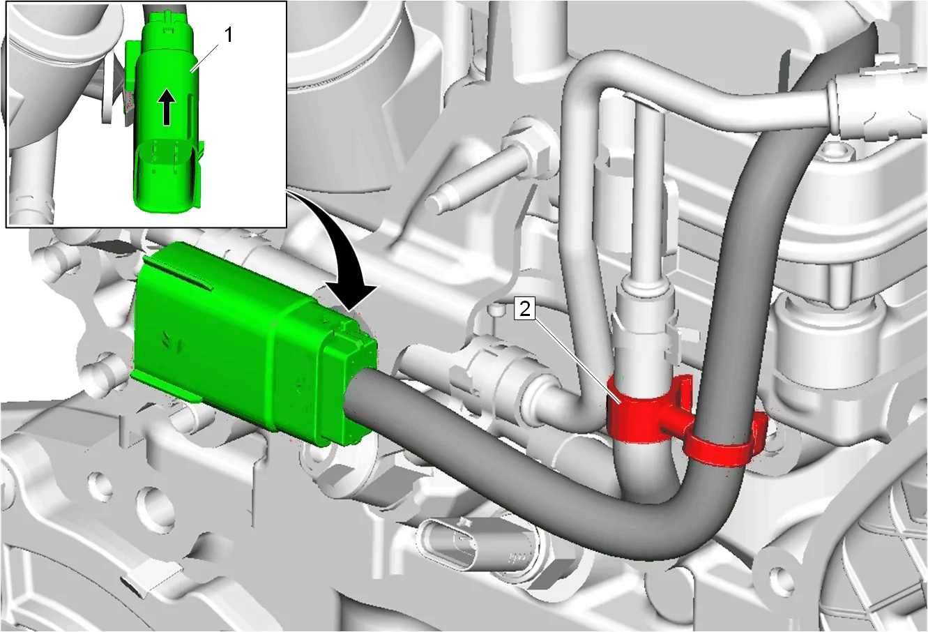
- Remove the fuel injector wiring harness connector (1) from the engine coolant air bleed bracket.
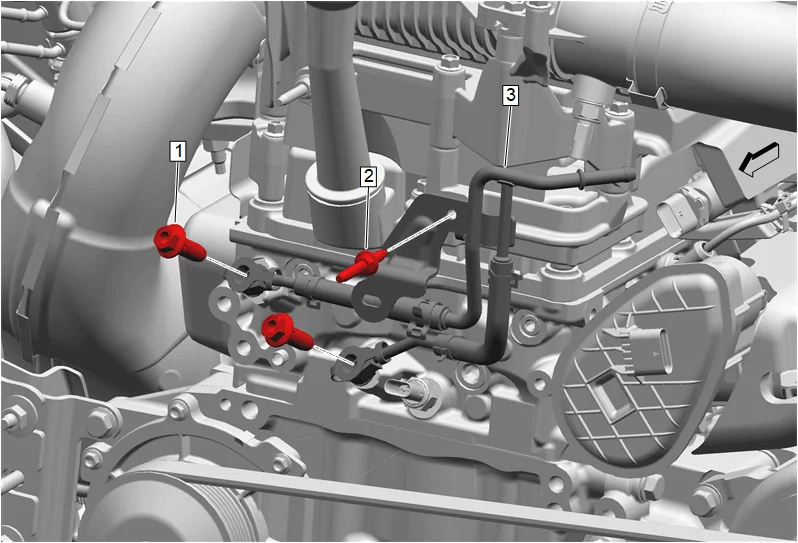
- Engine Coolant Air Bleed Pipe Bolt - Right Side Upper (1) » Remove
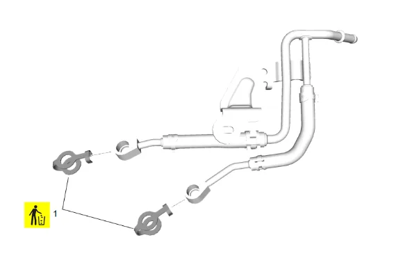
- Turbocharger Coolant Feed and Return Pipe Gasket - Right Side Upper (1) » Remove and DISCARD
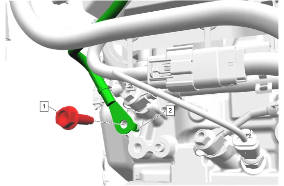
- { If equipped } Engine Wiring Harness Ground Bolt (1) » Remove
- { If equipped } Ground Cable (2) » Position aside
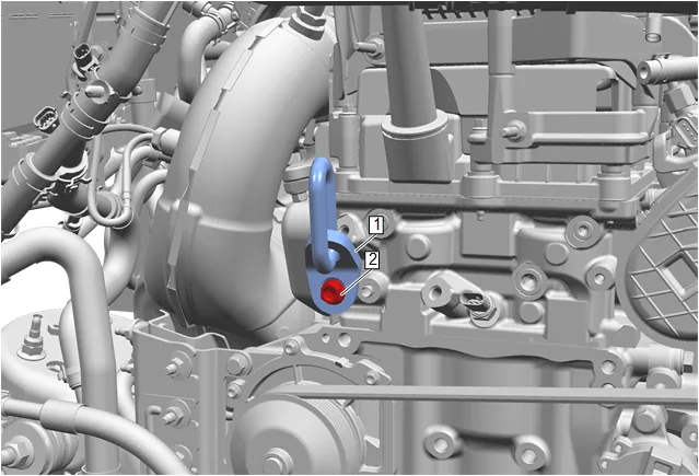
- Install the EN-36857 Engine Lift Bracket (1) to the front left side of the cylinder head as shown using the EN-51768 Engine Support Fixture Adaptor Bolt - M8 (2).
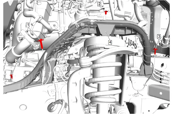
- Chassis Front Wiring Harness Bracket Bolt - Rear (1) » Remove
- Chassis Wiring Harness Front Bracket Retainer (2) » Remove [2x]
- Chassis Front Wiring Harness Bracket Bolt - Front (3) » Remove
- Remove the positive battery cable retainers from the chassis wiring harness front bracket.
- Chassis Wiring Harness (4) » Reposition
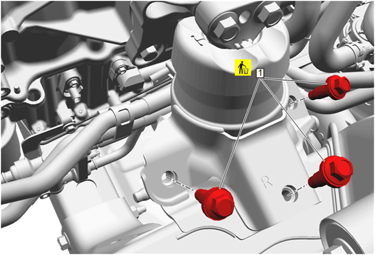
- Working through the wheelhouse opening, remove and DISCARD the 3 engine mount frame side bolts (1).
- Raise the engine with a suitable lifting device to remove the engine mount.
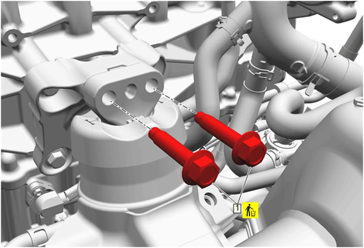
- Remove and DISCARD the 2 engine mount engine side bolts (1).
- Disconnect electrical connector at the rear of engine mount.
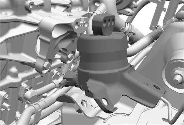
- Engine Mount (1) » Remove Cleaning and Inspection Procedure - Conditional
-
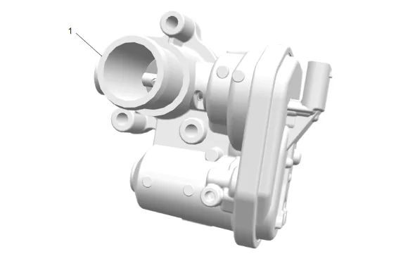
Clean the exhaust gas recirculation valve (1).
-
Inspect the exhaust gas recirculation valve (1).
-
Replace the exhaust gas recirculation valve (1) if any damage is found. Installation Procedure
-
Engine Mount (1) » Install
-
Connect electrical connector at the rear of engine mount.
-
If a NEW threaded component is being installed, loosen the adhesive using a metal pick or similar tool before proceeding. If threaded component is reused, prepare the threaded component using the following steps: 3.1. Remove any loose cured adhesive from the external threads of the component using a lint free cloth. 3.2. Thread the cleaned component into the internal mating threads and remove to loosen trapped cured adhesive. 3.3. Apply thread locking adhesive to the external threads of the component. Adhesives, Fluids, Lubricants, and Sealers 3.4. Ensure there are no gaps in the thread locking adhesive once applied to the component.
-
Install and tighten the 2 NEW engine mount engine side bolts (1). Fastener Specifications
-
Lower the engine.
-
If a NEW threaded component is being installed, loosen the adhesive using a metal pick or similar tool before proceeding. If threaded component is reused, prepare the threaded component using the following steps: 6.1. Remove any loose cured adhesive from the external threads of the component using a lint free cloth. 6.2. Thread the cleaned component into the internal mating threads and remove to loosen trapped cured adhesive. 6.3. Apply thread locking adhesive to the external threads of the component. Adhesives, Fluids, Lubricants, and Sealers 6.4. Ensure there are no gaps in the thread locking adhesive once applied to the component.
-
Install and tighten the 3 NEW engine mount frame side bolts (1). Fastener Specifications
-
Chassis Wiring Harness (4) » Install
-
Install the positive battery cable retainers to the chassis wiring harness front bracket.
-
Chassis Front Wiring Harness Bracket Bolt - Front (3) » Install and tighten — Fastener Specifications
-
Chassis Front Wiring Harness Bracket Bolt - Rear (1) » Install and tighten — Fastener Specifications
-
Chassis Wiring Harness Front Bracket Retainer (2) » Install [2x]
-
Remove the EN-51768 Engine Support Fixture Adaptor Bolt - M8 and the EN-36857 Engine Lift Bracket (1) from the front of the left side cylinder head.
-
Turbocharger Coolant Feed and Return Pipe Gasket - Right Side Upper (1) » Install NEW
-
Engine Coolant Air Bleed Pipe Bolt - Right Side Upper (1) » Install and tighten — Fastener Specifications
-
{ If equipped } Ground Cable (2) » Install
-
{ If equipped } Engine Wiring Harness Ground Bolt (1) » Install and tighten — Ground Repair
-
Install the fuel injector wiring harness connector (1) to the engine coolant air bleed bracket.
-
Position the engine wiring harness channel (3) to the front of the engine.
-
Engine Wiring Harness Bracket Bolt (2) » Install and tighten — Fastener Specifications
-
Engine Wiring Harness Bracket Nut (1) » Install and tighten [2x] — Fastener Specifications
-
Catalytic Converter Brace Bracket (1) » Install
-
Catalytic Converter Brace Bracket Bolt (2) » Install and tighten [2x] — Fastener Specifications
-
Catalytic Converter Gasket (3) » Install NEW
-
Catalytic Converter Clamp (2) » Install NEW
-
Nitrogen Oxides Catalytic Converter (1) » Install
-
Install hoses and wiring harness as needed.
-
Catalytic Converter Brace Bracket Nut (1) » Tighten [2x] — Fastener Specifications
-
Fuel Cooler Coolant Cooler Inlet Hose » Install
-
Fuel Heater Inlet and Outlet Nut (1) » Install and tighten — Fastener Specifications
-
Catalytic Converter Brace Bracket Nut (1) » Tighten [2x] — Fastener Specifications
-
Catalytic Converter Brace Bracket Nut (1) » Install and tighten [2x] — Fastener Specifications
-
{ If equipped } Battery Negative Cable Extension Cable Strap (1) @ Catalytic Converter Brace Bracket » Install
-
{ If equipped } Catalytic Converter Brace Bracket Nut (2) » Install and tighten — Fastener Specifications
-
Install the exhaust gas recirculation cooler (1).
-
Exhaust Gas Recirculation Cooler Nut (1) » Install and tighten [4x] — Fastener Specifications
-
Connect the electrical connector at exhaust gas recirculation cooler.
-
Exhaust Gas Recirculation Cooler Inlet Pipe Gasket - Upper (4) » Install NEW
-
Exhaust Gas Recirculation Cooler Inlet Pipe Gasket - Lower (3) » Install NEW
-
Exhaust Gas Recirculation Pipe (2) » Install
-
Exhaust Gas Recirculation Cooler Inlet Pipe Bolt (1) » Install and tighten [4x] — Fastener Specifications
-
Exhaust Gas Recirculation Valve Cooler Gasket (2) » Install NEW
-
Install the exhaust gas recirculation valve (1) with the exhaust gas recirculation valve hose.
-
Exhaust Gas Recirculation Pipe Bolt (1) » Install and tighten [2x] — Fastener Specifications
-
Heater Inlet Hose Bracket (2) » Install
-
Exhaust Gas Recirculation Valve Bracket Nut (1) » Install and tighten — Fastener Specifications
-
Exhaust Gas Recirculation Pipe Bolt (2) » Install and tighten [2x] — Fastener Specifications
-
Connect the electrical connector (1).
-
Exhaust Gas Recirculation Outlet Pipe Gasket (2) » Install NEW
-
Exhaust Gas Recirculation Pipe (1) » Install
-
Exhaust Gas Recirculation Pipe Nut (1) » Install and tighten — Fastener Specifications
-
Exhaust Gas Recirculation Pipe Nut (1) » Install and tighten — Fastener Specifications
-
Position the exhaust pressure differential sensor bracket (2) into place.
-
Exhaust Pressure Differential Sensor Bracket Stud (1) » Install and tighten [2x] — Fastener Specifications
-
Install the rear engine wiring harness channel (2).
-
Install the 3 rear engine wiring harness channel nuts (1).
-
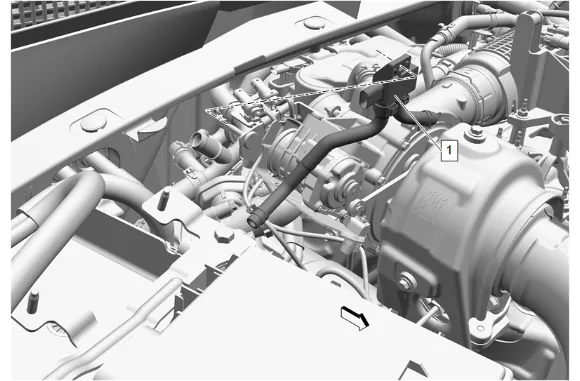
Exhaust Pressure Differential Sensor (1) » Install
-
Install the exhaust pressure differential sensor (2) to the exhaust gas recirculation cooler by engaging the hose clamp (1). Hose Clamp Replacement Guidelines - Spring Type
-
Install the exhaust pressure differential sensor to the exhaust gas recirculation valve hose by engaging the hose clamp (1). Hose Clamp Replacement Guidelines - Spring Type
-
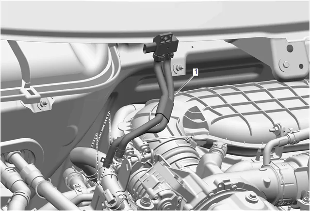
Exhaust Pressure Differential Sensor (1) » Install
-
Exhaust Pressure Sensor Hose Clamp (1) » Engage [2x] — Hose Clamp Replacement Guidelines - Spring Type
-
Exhaust Gas Recirculation Cooler Inlet Pipe (1) » Install
-
Exhaust Gas Recirculation Pipe Bracket Bolt (1) » Install and tighten [2x] — Fastener Specifications
-
Turbocharger Coolant Feed and Return Pipe (4) @ Exhaust Gas Recirculation Cooler Inlet Pipe » Install
-
Exhaust Gas Recirculation Valve Cooling Return Hose (3) @ Exhaust Gas Recirculation Cooler Inlet Pipe » Install
-
Hose Clamp (1) » Engage [2x] — Hose Clamp Replacement Guidelines - Spring Type
-
Thermostat Bypass Hose (2) @ Exhaust Gas Recirculation Cooler Inlet Pipe » Install
-
Hose Clamp (1) » Engage — Hose Clamp Replacement Guidelines - Spring Type
-
Exhaust Gas Recirculation Cooler Inlet Pipe (5) @ Exhaust Gas Recirculation Cooler Inlet Pipe » Install
-
Exhaust Gas Recirculation Cooler Outlet Pipe (4) @ Exhaust Gas Recirculation Cooler Inlet Pipe » Install
-
Heater Inlet Hose (3) @ Exhaust Gas Recirculation Cooler Inlet Pipe » Install
-
Exhaust Gas Recirculation Coolant Return Pipe (2) @ Exhaust Gas Recirculation Cooler Inlet Pipe » Install
-
Hose Clamp (1) » Engage [4x] — Hose Clamp Replacement Guidelines - Spring Type
-
Exhaust Gas Recirculation Valve Inlet Gasket (2) » Install NEW
-
Exhaust Back Pressure Valve (1) » Install
-
Catalytic Converter Nut (1) » Install and tighten [3x] — Fastener Specifications
-
Turbocharger Coolant Feed and Return Pipe Gasket (3) » Install NEW
-
Exhaust Gas Recirculation Valve Cooling Return Pipe (2) » Install
-
Exhaust Gas Recirculation Valve Cooling Return Pipe Bolt (1) » Install and tighten [2x] — Fastener Specifications
-
Electrical Connector (1) @ Exhaust Back Pressure Valve » Connect
-
Connect wiring harness retainers, as required.
-
Exhaust System Front Gasket (2) » Install NEW
-
Nitrogen Oxides Catalytic Converter (1) » Install
-
Exhaust Front Pipe Nut (1) » Install and tighten [2x] — Fastener Specifications
-
Catalytic Converter Brace Bracket (3) » Install
-
Catalytic Converter Brace Bracket Nut (1) » Install and tighten [2x] — Fastener Specifications
-
Wiring Harness Retainer (2) @ Catalytic Converter Brace Bracket (3) » Install
-
Exhaust Front Pipe Nut (1) » Install and tighten [2x] — Fastener Specifications
-
Exhaust Pipe Clamp (1) » Tighten — Fastener Specifications
-
Coat the threads of the exhaust particulate sensor (1) with anti-seize compound. Adhesives, Fluids, Lubricants, and Sealers
-
Exhaust Particulate Sensor (1) » Install and tighten — Fastener Specifications
-
Coat the threads with of the nitrogen oxides sensor – position 3 (1) with anti-seize compound. Adhesives, Fluids, Lubricants, and Sealers
-
Nitrogen Oxides Sensor - Position 3 (1) » Install and tighten — Fastener Specifications
-
Coat the threads with of the nitrogen oxides sensor – position 2 (1) with anti-seize compound. Adhesives, Fluids, Lubricants, and Sealers
-
Nitrogen Oxides Sensor - Position 2 (1) » Install and tighten — Fastener Specifications
-
Exhaust Gas Temperature Sensor(1) » Install and tighten — Fastener Specifications
-
Front Wheelhouse Liner - Right Side (3) » Install — Front Wheelhouse Liner Replacement
-
Exhaust System Front Gasket (3) » Install NEW
-
Reductant Fluid Injector (2) » Install
-
Emission Reduction Fluid Injector Clamp (1) » Install NEW — Fastener Specifications
-
Exhaust Temperature Sensor - Position 2 (1) » Install — Fastener Specifications
-
Exhaust Temperature Sensor - Position 1 (1) » Install — Fastener Specifications
-
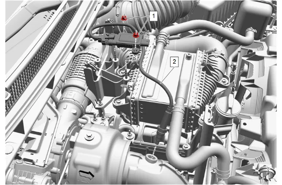
Coat the threads of the nitrogen oxides sensor (2) with anti-seize compound. Adhesives, Fluids, Lubricants, and Sealers
-
Nitrogen Oxides Sensor (2) » Install and tighten — Fastener Specifications
-
Catalytic Converter Clamp (1) » Tighten — Fastener Specifications
-
Turbocharger Heat Shield (1) » Install
-
Turbocharger Heat Shield Nut (2) » Install and tighten — Fastener Specifications
-
Turbocharger Heat Shield Bolt (1) » Install and tighten [2x] — Fastener Specifications
-
Exhaust Gas Recirculation Temperature Sensor (2) » Install and tighten — Fastener Specifications
-
Battery Tray (1) » Install
-
Engage all wire harness retainers to the battery tray.
-
Battery Tray Bolt (1) » Install and tighten [7x] — Fastener Specifications
-
Air Conditioning Evaporator Thermal Expansion Valve Seal - Small (4) » Install NEW
-
Air Conditioning Evaporator Thermal Expansion Valve Seal - Large (3) » Install NEW
-
Air Conditioning Refrigerant Heat Exchanger (2) » Install
-
Air Conditioning Evaporator Thermal Expansion Valve Hose Nut (1) » Install and tighten — Fastener Specifications
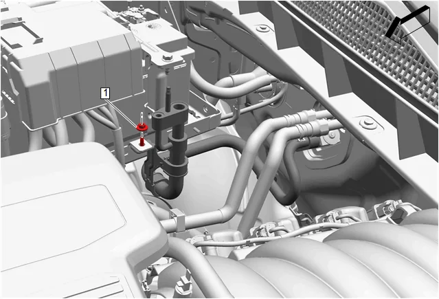
- Air Conditioning Refrigerant Heat Exchanger Nut (1) @ Battery Tray » Install and tighten — Fastener Specifications
-
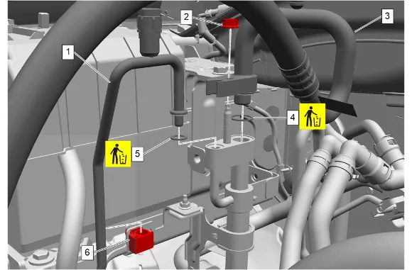
Air Conditioning Compressor and Condenser Hose Seal (5) » Install NEW
-
Air Conditioning Condenser and Evaporator Hose (1) » Install
-
Air Conditioning Condenser and Evaporator Hose Clip (6) » Install
-
Air Conditioning Compressor and Condenser Hose Seal (4) » Install NEW
-
Air Conditioning Compressor and Condenser Hose (3) @ Air Conditioning Refrigerant Heat Exchanger » Install
-
Air Conditioning Compressor and Condenser Hose Nut (2) @ Air Conditioning Refrigerant Heat Exchanger » Install and tighten — Fastener Specifications
-
Engine Wiring Harness Fuse Block Bracket (3) » Install
-
Retaining Tab (1) » Engage
-
Engine Wiring Harness Fuse Block Bracket Bolt (2) » Install and tighten [2x] — Fastener Specifications
-
Electrical Connector (1) » Install [4x]
-
Engine Wiring Harness Junction Block (3) » Install
-
Retaining Tab (1) » Engage [4x]
-
Engine Wiring Harness Junction Block Bolt (2) » Tighten [4x] — Fastener Specifications
-
Starter Solenoid Cable (4) » Install
-
Battery Positive Cable Nut (3) » Install and tighten — Fastener Specifications
-
Engine Wiring Harness Junction Block Cover (2) » Install
-
Retaining Tab (1) » Engage [2x]
-
Battery (1) » Install
-
Battery Hold Down Retainer (2) » Install
-
Battery Hold Down Retainer Bolt (1) » Install and tighten — Fastener Specifications
-
Battery Distribution Engine Compartment Fuse Block (2) » Install
-
Retaining Tab (1) » Engage [3x]
-
Battery Positive Post Clamp Nut (1) » Tighten — Fastener Specifications
-
Electrical Connector (1) » Connect
-
Front Compartment Fuse Block Cover (2) » Install
-
Retaining Tab (1) » Engage [2x]
-
Battery Hold Down Strap (2) » Install
-
If NEW threaded components are being installed, loosen the adhesive using a metal pick or similar tool before proceeding. If threaded components are reused, prepare the threaded components using the following steps: 145.1. Remove any loose cured adhesive from the external threads of the components using a lint free cloth. 145.2. Thread the cleaned components into the internal mating threads and remove to loosen trapped cured adhesive. 145.3. Apply thread locking adhesive to the external threads of the components. Adhesives, Fluids, Lubricants, and Sealers 145.4. Ensure there are no gaps in the thread locking adhesive once applied to the component.
-
Battery Hold Down Strap Bolt (1) » Install and tighten [2x] — Fastener Specifications
-
Air Cleaner Outlet Duct (2) » Install
-
Air Cleaner Outlet Duct Clamp (1) » Tighten [2x] — Fastener Specifications
-
Air Cleaner Outlet Front Duct (2) » Install
-
Air Cleaner Outlet Duct Clamp (1) » Tighten [2x] — Fastener Specifications
-
Oil Filler Cap » Remove
-
Intake Manifold Cover (2) » Install
-
Intake Manifold Cover Bolt (1) » Install and tighten — Fastener Specifications
-
Oil Filler Cap » Install
-
Plenum Front Panel Outer Reinforcement (1) » Install — Plenum Front Panel Outer Reinforcement Removal and Installation
-
Fill the cooling system to the proper level. Cooling System Draining and Filling
-
Recharge the refrigerant. Refrigerant Recovery and Recharging
-
Inspect the exhaust system for leaks.