Differential Carrier Bushing Replacement - Rear (G86)
Single Use Fasteners and Components Differential Carrier Front Bolt Differential Carrier Bushing [2x] Special Tools DT-52899 Rear Drive Module Mount Bushing Replacer Equivalent regional tools: Special Tools Removal Procedure
- Raise and support the vehicle. Lifting and Jacking the Vehicle
- Remove the spare tire.
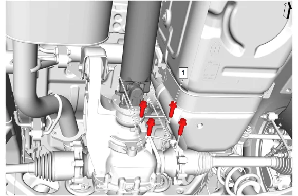
- Rear Propeller Shaft Bolt (1) » Remove [4x]
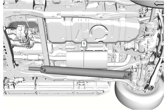
- Propeller Shaft (1) » Remove
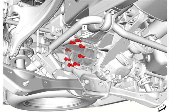
- Rear Wheel Drive Shaft Bolt (1) » Remove [8x]
- Reposition the right rear wheel drive shaft downward.
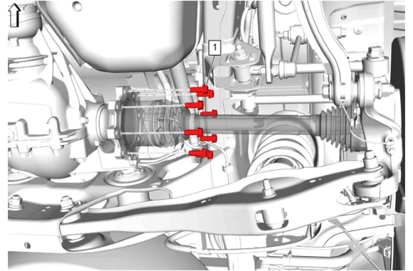
- Rear Wheel Drive Shaft Bolt (1) » Remove [8x]
- Reposition the left rear wheel drive shaft downward.
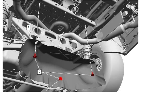
- {If equipped} with dual exhaust. 9.1. Spare Wheel Heat Shield Bolt (2) » Remove [3x] 9.2. Spare Wheel Heat Shield (1) » Remove
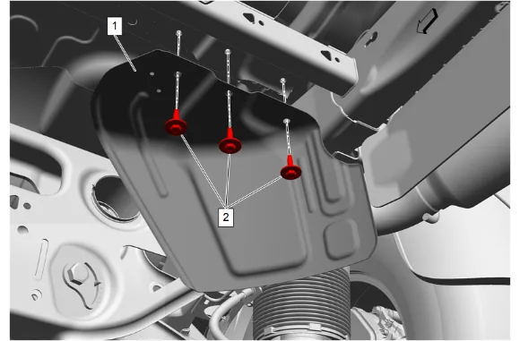
- {If equipped} with single exhaust. 10.1. Spare Wheel Heat Shield Bolt (2) » Remove [3x] 10.2. Spare Wheel Heat Shield (1) » Remove
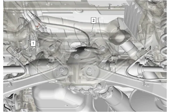
- Rear Axle Vent Hose (2) » Disconnect
- Support the rear differential carrier.
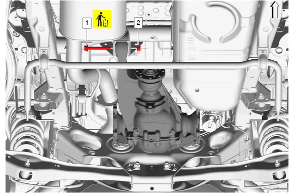
- Differential Carrier Nut (2) » Remove
- Differential Carrier Front Bolt (1) » Remove and DISCARD
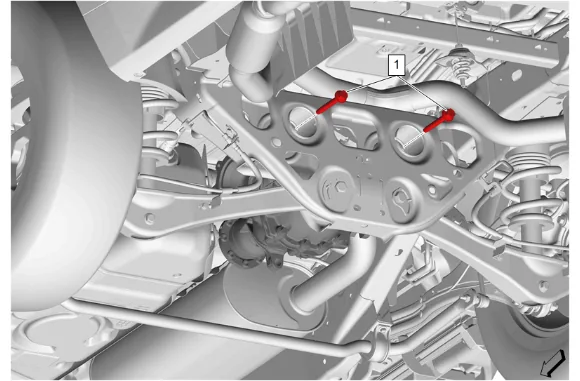
- Differential Carrier Rear Bolt (1) » Remove [2x]
- Lower the rear differential carrier.

- Using the DT-52899 Rear Drive Module Mount Bushing Replacer (2), Remove and DISCARD the 2 differential carrier bushing (1) Installation Procedure
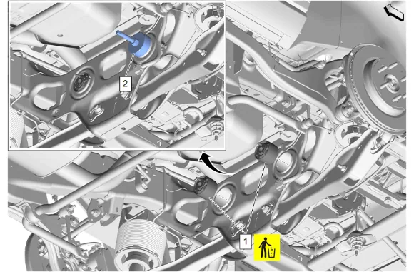
- Using the DT-52899 Rear Drive Module Mount Bushing Replacer (2), Install NEW the 2 differential carrier bushing (1)
- Raise the differential carrier.
-
Differential Carrier Rear Bolt (1) » Install and tighten [2x] — Fastener Specifications
-
Differential Carrier Front Bolt (1) » Install NEW
-
Differential Carrier Nut (2) » Install and tighten — Fastener Specifications
-
Remove support from the rear differential carrier.
-
Rear Axle Vent Hose (2) » Connect
-
{If equipped} with dual exhaust. 8.1. Spare Wheel Heat Shield (1) » Install 8.2. Spare Wheel Heat Shield Bolt (2) » Install and tighten [3x] — Fastener Specifications
-
{If equipped} with single exhaust. 9.1. Spare Wheel Heat Shield (1) » Install 9.2. Spare Wheel Heat Shield Bolt (2) » Install and tighten [3x] — Fastener Specifications
-
If NEW threaded components are being installed, loosen the adhesive using a metal pick or similar tool before proceeding. If threaded components are reused, prepare the threaded components using the following steps: 10.1. Remove any loose cured adhesive from the external threads of the components using a lint free cloth. 10.2. Thread the cleaned components into the internal mating threads and remove to loosen trapped cured adhesive. 10.3. Apply thread locking adhesive to the external threads of the components. Adhesives, Fluids, Lubricants, and Sealers 10.4. Ensure there are no gaps in the thread locking adhesive once applied to the component.
-
Reposition the right rear wheel drive shaft.
-
Rear Wheel Drive Shaft Bolt (1) » Install and tighten [8x] — Fastener Specifications
-
If NEW threaded components are being installed, loosen the adhesive using a metal pick or similar tool before proceeding. If threaded components are reused, prepare the threaded components using the following steps: 13.1. Remove any loose cured adhesive from the external threads of the components using a lint free cloth. 13.2. Thread the cleaned components into the internal mating threads and remove to loosen trapped cured adhesive. 13.3. Apply thread locking adhesive to the external threads of the components. Adhesives, Fluids, Lubricants, and Sealers 13.4. Ensure there are no gaps in the thread locking adhesive once applied to the component.
-
Reposition the left rear wheel drive shaft.
-
Rear Wheel Drive Shaft Bolt (1) » Install and tighten [8x] — Fastener Specifications
-
Propeller Shaft (1) » Install
-
If NEW threaded components are being installed, loosen the adhesive using a metal pick or similar tool before proceeding. If threaded components are reused, prepare the threaded components using the following steps: 17.1. Remove any loose cured adhesive from the external threads of the components using a lint free cloth. 17.2. Thread the cleaned components into the internal mating threads and remove to loosen trapped cured adhesive. 17.3. Apply thread locking adhesive to the external threads of the components. Adhesives, Fluids, Lubricants, and Sealers 17.4. Ensure there are no gaps in the thread locking adhesive once applied to the component.
-
Rear Propeller Shaft Bolt (1) » Install and tighten [4x] — Fastener Specifications
-
Install the spare tire.
-
Remove the support and lower the vehicle.