Instrument Panel Outer Air Outlet Duct Replacement - Left Side (with UV6)
Instrument Panel Outer Air Outlet Duct Replacement - Left Side (with UV6) Removal Procedure
- Disable the SIR system. SIR Disabling and Enabling
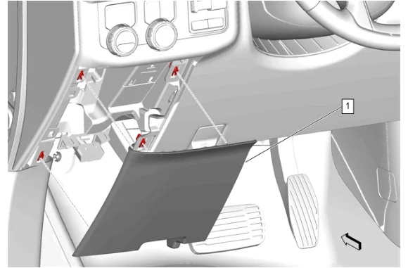
- Instrument Panel Lower Trim Panel Outer Filler (1) » Remove
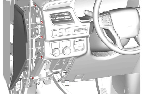
- Using a flat-bladed plastic trim tool, release the retaining clips.
- Instrument Panel Fuse Block Access Hole Cover (1) » Remove
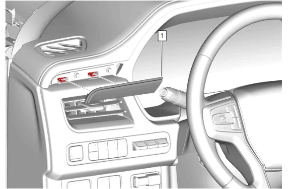
- Using a flat-bladed plastic trim tool, release the retaining clips.
- Instrument Panel Trim Plate Applique (1) » Remove
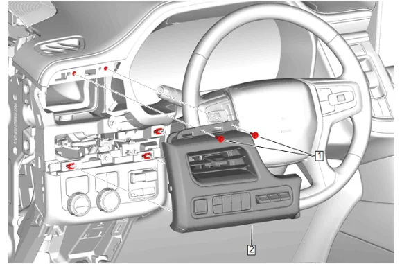
- Instrument Panel Trim Pad Bolt (1) » Remove [2x]
- Instrument Panel Trim Pad (2) » Remove
- Disconnect the electrical connectors.
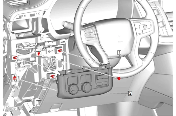
- Instrument Panel Switch Trim Plate Bolt (1) » Remove
- Disconnect the electrical connectors.
- Instrument Panel Switch Trim Plate (2) » Remove
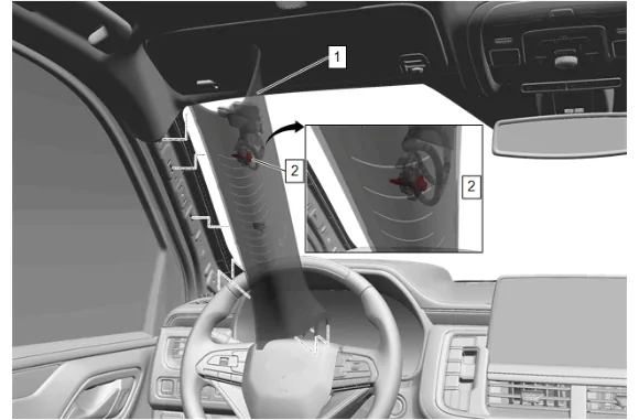
- Pull down the windshield garnish molding (1) rearwards to release the tether from the A pillar.
- Access the windshield garnish bolt (2) which is located on the backside of the windshield garnish molding (1) and secures the tether to the A pillar.
- Windshield Garnish Molding Bolt (2) » Remove
- Windshield Garnish Molding (1) » Remove
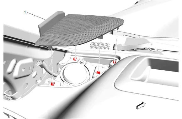
- Using a flat-bladed plastic trim tool, release the retaining clips.
- Radio Front Speaker Grille (1) » Remove
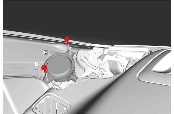
- Radio Front Speaker Bolt (1) » Remove [2x]
- Radio Front Speaker (2) » Remove
- Disconnect the electrical connector.
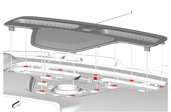
- Using a flat-bladed plastic trim tool, release the retaining clips.
- Instrument Panel Extension (1) » Remove
- Disconnect the electrical connector.
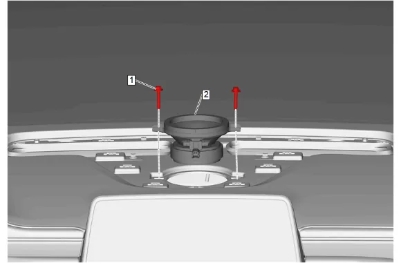
- Radio Front Center Speaker Bolt (1) » Remove [2x]
- Radio Front Center Speaker (2) » Remove
- Disconnect the electrical connector.
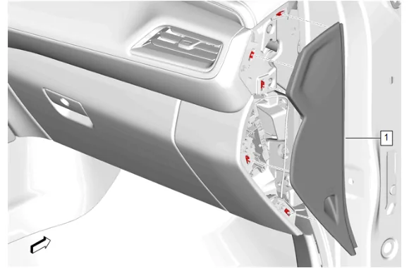
- Using a flat-bladed plastic trim tool, release the retaining clips.
- Instrument Panel Fuse Block Access Hole Cover (1) » Remove
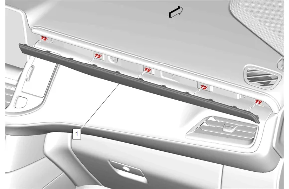
- Using a flat-bladed plastic trim tool, release the retaining clips.
- Instrument Panel Trim Plate Applique (1) » Remove
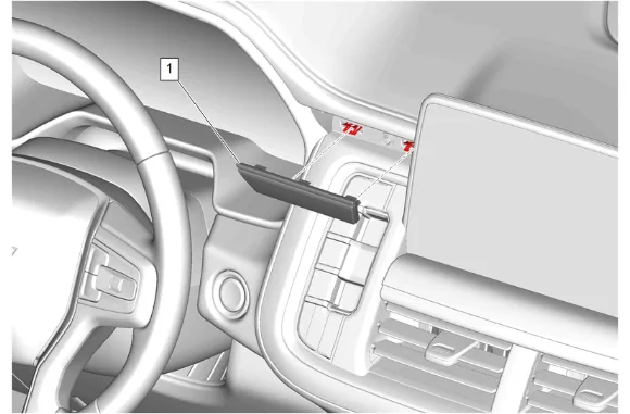
- Using a flat-bladed plastic trim tool, release the retaining clips.
- Instrument Panel Center Trim Plate Applique (1) » Remove
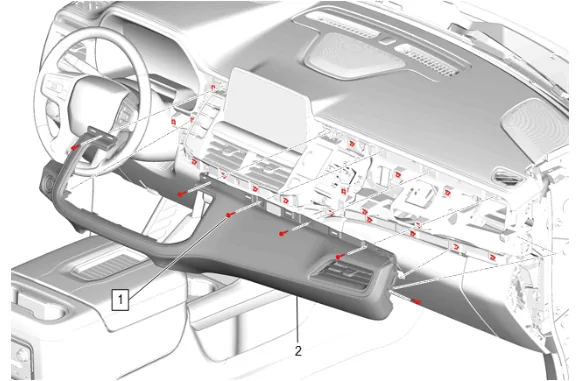
- Instrument Panel Upper Trim Panel Bolt (1) » Remove [6x]
- Using a flat-bladed plastic trim tool, release the retaining clips.
- Instrument Panel Trim Pad (2) » Remove
- Disconnect the electrical connector.
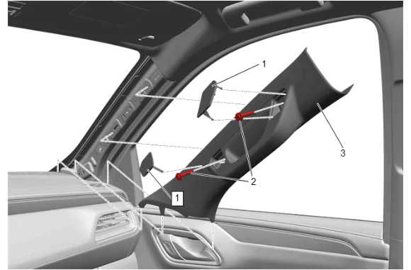
- Windshield Pillar Assist Handle Cover (1) » Remove [2x]
- Windshield Pillar Assist Handle Bolt (2) » Remove [2x]
- Windshield Garnish Molding (3) » Remove
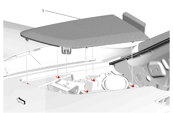
- Using a flat-bladed plastic trim tool, release the retaining clips.
- Radio Front Speaker Grille (1) » Remove
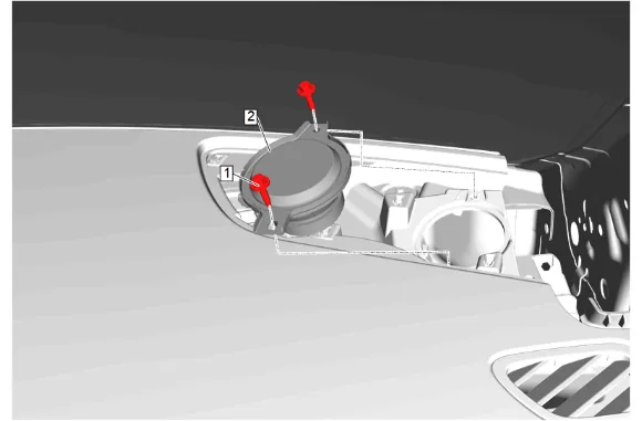
- Radio Front Speaker Bolt (1) » Remove [2x]
- Radio Front Speaker (2) » Remove
- Disconnect the electrical connector.
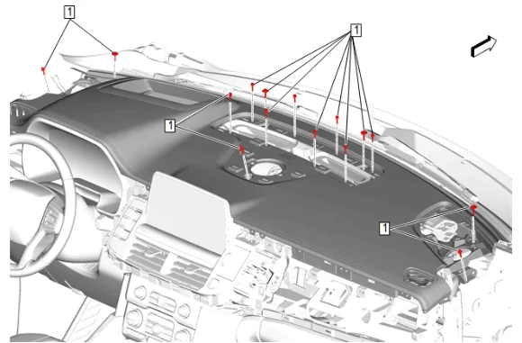
- Instrument Panel Upper Trim Panel Bolt (1) » Remove [15x]
- Disconnect the electrical connector.
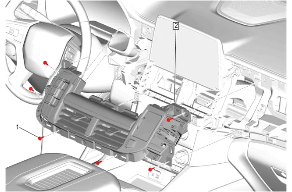
- Instrument Panel Center Trim Panel Bolt (1) » Remove [6x]
- Instrument Panel Transmission Shift Opening Cover (2) » Remove
- Disconnect the electrical connectors.
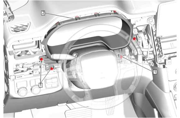
- Instrument Panel Cluster Trim Plate Bolt (1) » Loosen [4x]
- Using a flat-bladed plastic trim tool, release the retaining clips.
- Instrument Panel Cluster Trim Plate (2) » Loosen
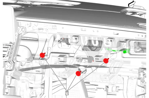
- Instrument Panel Airbag Bolt (1) » Remove [3x]
- Disconnect the electrical connector.
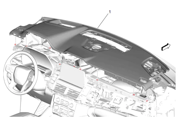
- Instrument Panel Upper Trim Panel (1) » Remove
- With the aid of an assistant remove the instrument panel upper trim panel (1) from the vehicle.
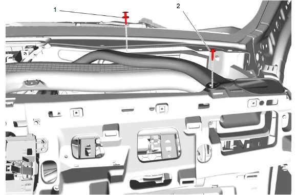
- Side Window Defogger Outlet Duct Retainer (1) » Remove
- Side Window Defogger Outlet Duct Bolt (2) » Remove
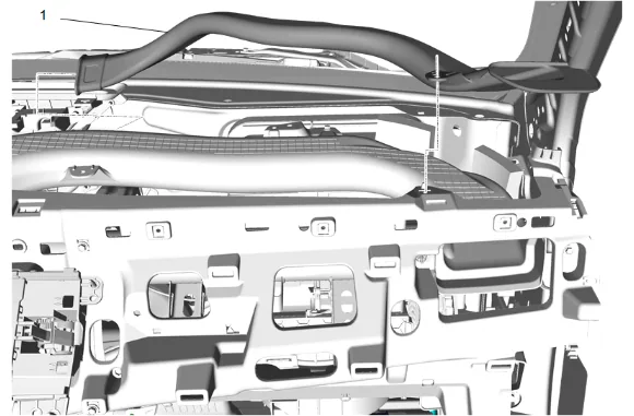
- Side Window Defogger Outlet Duct - Right Side (1) » Remove
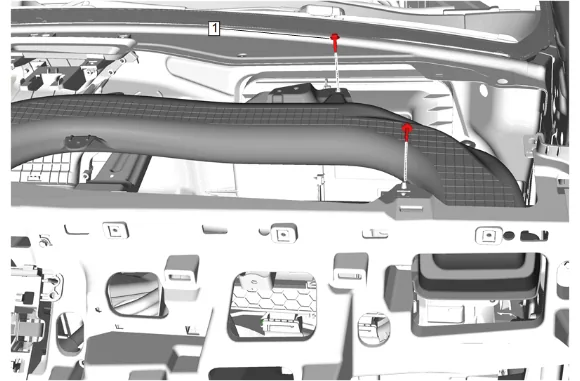
- Instrument Panel Outer Air Outlet Bolt (1) » Remove [2x]
- Remove the wiring harness retainers form the right instrument panel outer air outlet duct.
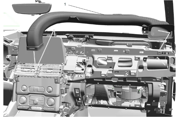
- Instrument Panel Outer Air Outlet Duct - Right Side (1) » Remove
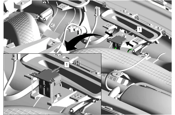
- Release the retaining tabs.
- Disconnect the electrical connector.
- Auxiliary Wireless Communication Interface Antenna (1) » Remove
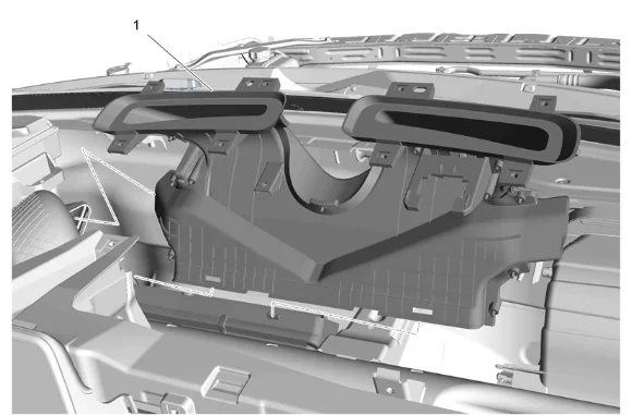
- Pull the windshield defroster outlet duct (1) towards the rear of the car while moving up and to the right to disconnect the left side window defogger outlet duct, to remove the duct.
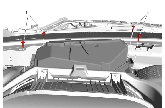
- Head-Up Display Bolt (1) » Remove [4x]
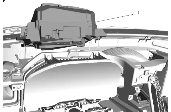
- Disconnect the electrical connectors.
- Maneuver the head- up display (1) out from behind the instrument panel carrier.
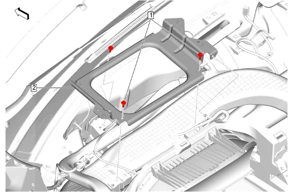
- Head-Up Display Bracket Bolt (1) » Remove [3x]
- Disconnect and reposition wiring harness as necessary.
- Head-Up Display Bracket (2) » Remove
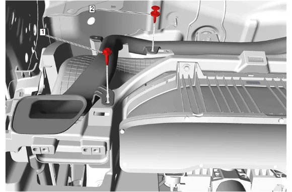
- Side Window Defogger Outlet Duct Bolt (1) » Remove
- Side Window Defogger Outlet Duct Retainer (2) » Remove
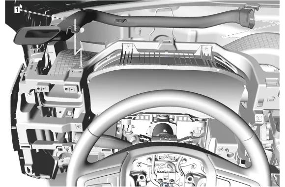
- Side Window Defogger Outlet Duct - Left Side (1) » Remove
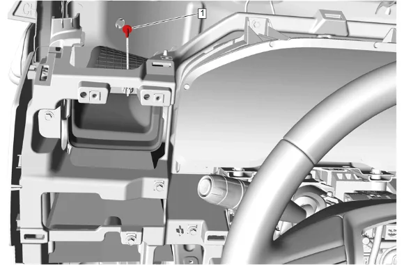
- Instrument Panel Outer Air Outlet Duct Bolt (1) » Remove
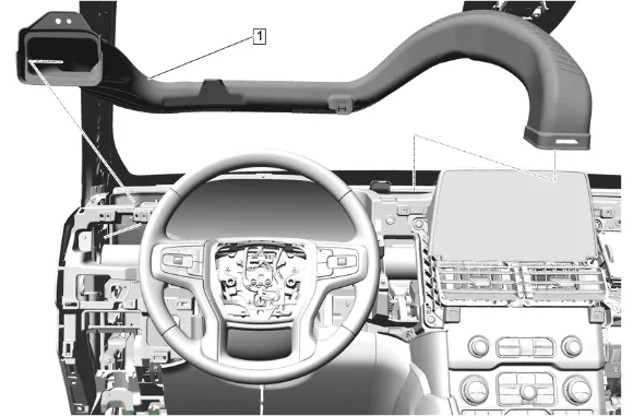
-
Instrument Panel Outer Air Outlet Duct - Left Side (1) » Remove Installation Procedure
-
Instrument Panel Outer Air Outlet Duct - Left Side (1) » Install
-
Instrument Panel Outer Air Outlet Duct Bolt (1) » Install and tighten — Fastener Specifications
-
Side Window Defogger Outlet Duct - Left Side (1) » Install
-
Side Window Defogger Outlet Duct Bolt (1) » Install and tighten — Fastener Specifications
-
Side Window Defogger Outlet Duct Retainer (2) » Install
-
Head-Up Display Bracket (2) » Install
-
Connect and return the wiring harness to its original routing.
-
Head-Up Display Bracket Bolt (1) » Install and tighten [3x] — Fastener Specifications
-
Maneuver the head- up display (1) back behind the instrument panel carrier.
-
Connect the electrical connectors.
-
Head-Up Display Bolt (1) » Install and tighten [4x] — Fastener Specifications
-
Install the windshield defroster outlet (1) duct while connecting the left side window defogger outlet duct.
-
Connect the electrical connector.
-
Auxiliary Wireless Communication Interface Antenna (1) » Install
-
Secure the retaining tabs.
-
Instrument Panel Outer Air Outlet Duct - Right Side (1) » Install
-
Instrument Panel Outer Air Outlet Bolt (1) » Install and tighten [2x] — Fastener Specifications
-
Install the wiring harness retainers onto the right instrument panel outer air outlet duct.
-
Side Window Defogger Outlet Duct - Right Side (1) » Install
-
Side Window Defogger Outlet Duct Bolt (2) » Install and tighten — Fastener Specifications
-
Side Window Defogger Outlet Duct Retainer (1) » Install
-
With the aid of an assistant install the instrument panel upper trim panel (1) into the vehicle.
-
Connect the electrical connector.
-
Instrument Panel Upper Trim Panel (1) » Install
-
Connect the electrical connector.
-
Instrument Panel Airbag Bolt (1) » Install and tighten [3x] — Fastener Specifications
-
Instrument Panel Cluster Trim Plate (2) » Install
-
Instrument Panel Cluster Trim Plate Bolt (1) » Install and tighten [4x] — Fastener Specifications
-
Connect the electrical connectors.
-
Instrument Panel Transmission Shift Opening Cover (2) » Install
-
Instrument Panel Center Trim Panel Bolt (1) » Install and tighten [6x] — Fastener Specifications
-
Instrument Panel Upper Trim Panel Bolt (1) » Install and tighten [15x] — Fastener Specifications
-
Connect the electrical connector.
-
Radio Front Speaker (2) » Install
-
Radio Front Speaker Bolt (1) » Install and tighten [2x] — Fastener Specifications
-
Radio Front Speaker Grille (1) » Install
-
Windshield Garnish Molding (3) » Install
-
Windshield Pillar Assist Handle Bolt (2) » Install and tighten [2x] — Fastener Specifications
-
Windshield Pillar Assist Handle Cover (1) » Install [2x]
-
Connect the electrical connector.
-
Instrument Panel Trim Pad (2) » Install
-
Instrument Panel Upper Trim Panel Bolt (1) » Install and tighten [6x] — Fastener Specifications
-
Instrument Panel Center Trim Plate Applique (1) » Install
-
Instrument Panel Trim Plate Applique (1) » Install
-
Instrument Panel Fuse Block Access Hole Cover (1) » Install
-
Connect the electrical connector.
-
Radio Front Center Speaker (2) » Install
-
Radio Front Center Speaker Bolt (1) » Install and tighten [2x] — Fastener Specifications
-
Connect the electrical connector.
-
Instrument Panel Extension (1) » Install
-
Connect the electrical connector.
-
Radio Front Speaker (2) » Install
-
Radio Front Speaker Bolt (1) » Install and tighten [2x] — Fastener Specifications
-
Radio Front Speaker Grille (1) » Install
-
Windshield Garnish Molding Bolt (2) » Install and tighten — Fastener Specifications
-
Align the retaining clips with the slots in the A pillar and press the windshield garnish molding (1) into place.
-
Windshield Garnish Molding (1) » Install
-
Instrument Panel Switch Trim Plate (2) » Install
-
Connect the electrical connectors.
-
Instrument Panel Switch Trim Plate Bolt (1) » Install and tighten — Fastener Specifications
-
Connect the electrical connectors.
-
Instrument Panel Trim Pad (2) » Install
-
Instrument Panel Trim Pad Bolt (1) » Install and tighten [2x] — Fastener Specifications
-
Instrument Panel Trim Plate Applique (1) » Install
-
Instrument Panel Fuse Block Access Hole Cover (1) » Install
-
Instrument Panel Lower Trim Panel Outer Filler (1) » Install
-
Enable the SIR System. SIR Disabling and Enabling