Tire and Wheel Assembly Runout Measurement - Off Vehicle
Vibration Diagnosis and Correction | Diagnostic Information and Procedures | Document ID: 5039947 Tire and Wheel Assembly Runout Measurement - Off Vehicle
- Raise and support the vehicle.
- Mark the location of the wheels to the wheel studs and mark the specific vehicle position on each tire and wheel – LF, LR, RF, RR.
- Remove the tire and wheel assemblies from the vehicle. Tire and Wheel Removal and Installation
- Closely inspect each tire for proper and even bead seating.
- If any of the tire beads were not properly or evenly seated, reseat the tire bead, then proceed to step 6. Tire Dismounting and Mounting
- Mount a tire and wheel assembly on a spin-type wheel balancer. Follow the tire balancing machine manufacture installation instructions.
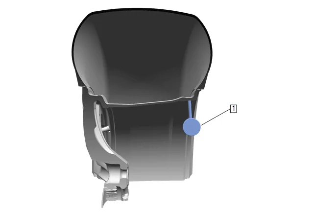
- Position the dial indicator (1) on the horizontal outer surface of the wheel rim flange – with the tire still mounted – such that the dial indicator is perpendicular to the rim flange surface. Wheel runout should be measured on both the inboard and outboard rim flanges, unless wheel design will not permit. Ignore any jumps or dips due to paint drips, chips, or welds.
- Slowly rotate the tire and wheel assembly one complete revolution in order to find the low spot.
- Set the dial indicator (1) to zero at the low spot.
- Slowly rotate the tire and wheel assembly one more complete revolution and measure the total amount of wheel radial runout. Specification Specification Maximum aluminum wheel radial runout – measured off-vehicle, tire mounted: 0.762 mm (0.030 in) Maximum steel wheel radial runout – measured off-vehicle, tire mounted: 1.015 mm (0.040 in)
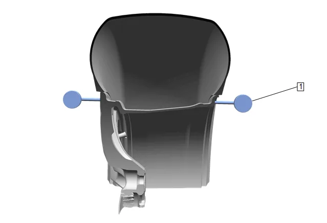
- Position the dial indicator (1) on the vertical outer surface of the wheel rim flange – with the tire still mounted – such that the dial indicator is perpendicular to the rim flange surface. Wheel runout should be measured on both the inboard and outboard rim flanges, unless wheel design will not permit. Ignore any jumps or dips due to paint drips, chips, or welds.
- Slowly rotate the tire and wheel assembly one complete revolution in order to find the low spot.
- Set the dial indicator (1) to zero at the low spot.
- Slowly rotate the tire and wheel assembly one more complete revolution and measure the total amount of wheel lateral runout. Specification Specification Maximum aluminum wheel lateral runout – measured off-vehicle, tire mounted: 0.762 mm (0.030 in) Maximum steel wheel lateral runout – measured off-vehicle, tire mounted: 1.143 mm (0.045 in)
- Repeat steps 19 through 26 until all of the wheel radial and lateral runout measurements have been taken on each of the – tire and wheel – assemblies with assembly runout measurements which were NOT within specifications.
- If any of the wheel runout measurements were NOT within specifications, proceed to Measuring Wheel Runout – Tire Dismounted.
- For any of the wheel runout measurements which WERE within specifications, while the – tire and wheel – assembly runout measurements were NOT within specifications, replace the tire, then balance the assembly. Tire and Wheel Assembly Balancing - Off Vehicle
- After replacement of any tires, always re-measure the runout of the affected tire and wheel assembly, or assemblies.
- Using the matchmarks made prior to removal, install the tire and wheel assemblies to the vehicle.
- Lower the vehicle. Wheel Runout Measurement – Tire Dismounted
- On the tire and wheel assembly, or assemblies with wheel runout measurements – tire mounted – which were NOT within specifications, mark each tire and wheel in relation to each other.
- Dismount the tire from the wheel.
- Mount the wheel on a spin-type wheel balancer.
- Locate the wheel on the balancer with a cone through the back side of the center pilot hole.
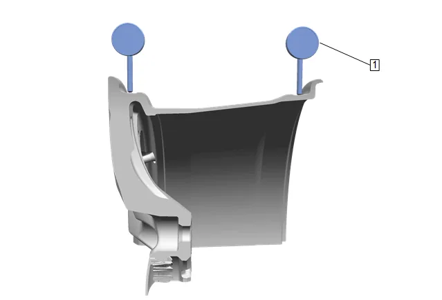
- Position the dial indicator (1) on the horizontal inner surface of the wheel rim flange – with the tire dismounted – such that the dial indicator is perpendicular to the rim flange surface. Wheel runout should be measured on both the inboard and outboard rim flanges. Ignore any jumps or dips due to paint drips, chips, or welds.
- Slowly rotate the wheel one complete revolution in order to find the low spot.
- Set the dial indicator (1) to zero at the low spot.
- Slowly rotate the wheel one more complete revolution and measure the total amount of wheel radial runout. Specification Specification Maximum aluminum wheel radial runout – measured off-vehicle, tire dismounted: 0.762 mm (0.030 in) Maximum steel wheel radial runout – measured off- vehicle, tire dismounted: 1.015 mm (0.040 in)
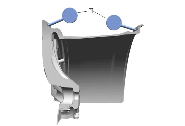
- Position the dial indicator (1) on the vertical inner surface of the wheel rim flange – with the tire dismounted – such that the dial indicator is perpendicular to the rim flange surface. Wheel runout should be measured on both the inboard and outboard rim flanges. Ignore any jumps or dips due to paint drips, chips, or welds.
- Slowly rotate the wheel one complete revolution in order to find the low spot.
- Set the dial indicator (1) to zero at the low spot.
- Slowly rotate the wheel one more complete revolution and measure the total amount of wheel lateral runout. Specification Specification Maximum aluminum wheel lateral runout – measured off-vehicle, tire dismounted: 0.762 mm (0.030 in) Maximum steel wheel lateral runout – measured off- vehicle, tire dismounted: 1.143 mm (0.045 in)
- Repeat steps 2 through 12 until all of the wheel radial and lateral runout measurements – tire dismounted – have been taken on each wheel with runout measurements – tire mounted – which were NOT within specifications.
- If any of the wheel runout measurements – tire dismounted – were NOT within specifications, replace the wheel. Always measure the runout of any replacement wheels.
- For any of the wheel runout measurements which WERE within specifications, while the – tire and wheel – assembly runout measurements were NOT within specifications, replace the tire, then balance the assembly. Tire and Wheel Assembly Balancing - Off Vehicle
- Using the matchmarks made prior to dismounting the tire, or tires, mount the tire, or tires to the wheel, or wheels, then balance the assembly, or assemblies. Tire and Wheel Assembly Balancing - Off Vehicle Always measure the runout of any of the tire and wheel assemblies which have had the tires dismounted and mounted.
- Using the matchmarks made prior to removal, install the tire and wheel assemblies to the vehicle.
- Lower the vehicle.