Engine Compression Test
Engine Mechanical - 3.0L LM2 Diesel | Diagnostic Information and Procedures | Document ID: 5527861 Single Use Fasteners and Components Glow Plug [6x] Special Tools EN-26999 Compression Gauge EN-46722 Compression Gauge Adapter Equivalent regional tools: Special Tools Technical Requirements Ensure that the vehicle battery is in good condition, and fully charged or the battery is connected to a battery charger. The battery voltage should be >12,5 V. Operate the vehicle until the engine is at normal operating temperature. The engine oil temperature should be >80°C (>176°F). Preliminary Procedures
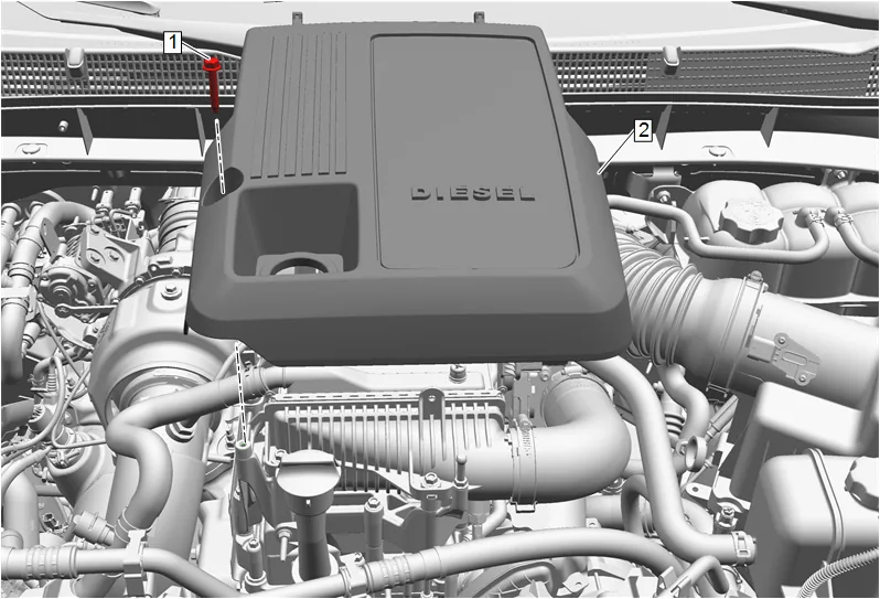
- Intake Manifold Cover Bolt (1) » Remove
- Intake Manifold Cover (2) » Remove
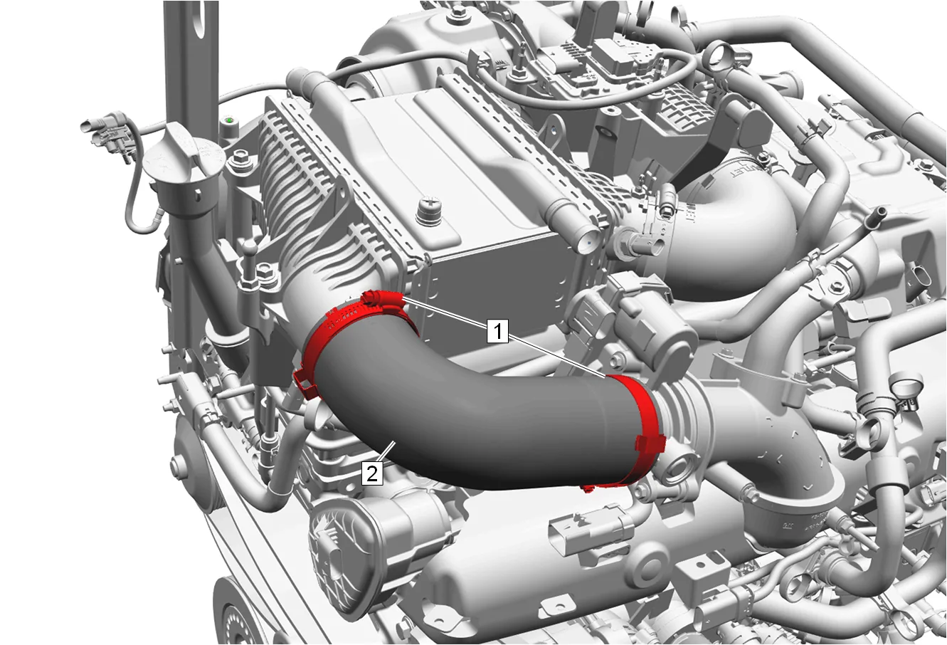
- Clamp (1) » Loosen [2x]
- Charge Air Cooler Outlet Air Hose (2) » Remove
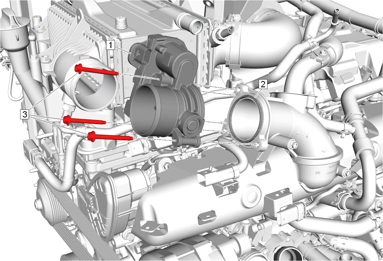
- Throttle Body Bolt (3) » Remove [3x]
- Throttle Body (1) » Position aside
- Throttle Body Gasket (2) » Remove and DISCARD
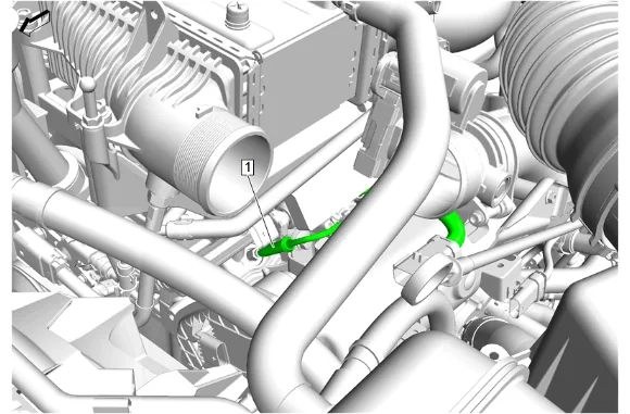
- Electrical Connector (1) @ Glow Plug » Disconnect [6x]
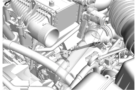
- Glow Plug (1) » Remove [6x]
- Inspect each glow plug tip and ensure the glow plug is not broken. If a broken tip is suspected, inspect the combustion chamber for the glow plug tip.
- Fuel Pump Relay » Remove For component location, refer to Engine Controls Schematics. For removal procedure, refer to Electrical Relay Replacement.
- Crank the engine with the starter motor for 5 seconds to remove any foreign substances from the cylinders.
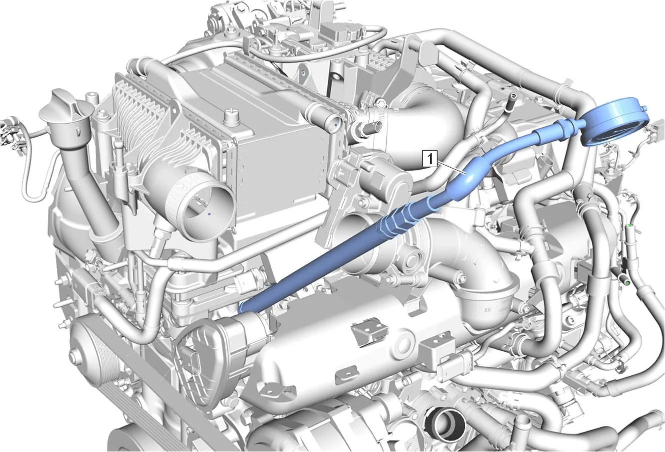
- Install the EN-26999 Compression Gauge and EN-46722 Compression Gauge Adapter in the glow plug hole for the cylinder being checked. Measurement Procedure
-
Check the compression of cylinder 1: 1.1. Turn the ignition ON, with the engine OFF. 1.2. Using the vehicle starter motor to crank the engine. 1.3. Observe the gauge and note the reading as the compression test is being performed.
-
Repeat the procedure for all remaining cylinders.
-
Compare the compression value of all cylinders.
-
The minimum compression in any cylinder is 1800 kPa (261 psi). There should not be more than 10 percent difference between a suspect cylinder and the average compression of all 6 cylinders.
-
If one or more cylinders fails to meet the specified compression range, refer to Cylinder Leakage Test to find the leakage. Subsequent Procedures
-
Fuel Pump Relay » Install For component location, refer to Engine Controls Schematics. For installation procedure, refer to Electrical Relay Replacement.
-
Remove the EN-26999 Compression Gauge and EN-46722 Compression Gauge Adapter from the glow plug hole.
-
Glow Plug (1) » Install and tighten [6x] — Fastener Specifications
-
Electrical Connector (1) @ Glow Plug » Connect [6x]
-
Throttle Body Gasket (2) » Install NEW
-
Throttle Body (1) » Install
-
Throttle Body Bolt (6) » Install and tighten [3x] — Fastener Specifications
-
Charge Air Cooler Outlet Air Hose (2) » Install
-
Clamp (1) » Install and tighten [2x] — Fastener Specifications
-
Intake Manifold Cover (2) » Install
-
Intake Manifold Cover Bolt (1) » Install and tighten — Fastener Specifications