Automatic Transmission Wiring Harness Replacement
Automatic Transmission - 10L80 MHS MQC | Repair Instructions - On Vehicle | Document ID: 5586298 Single Use Fasteners and Components Automatic Transmission Auxiliary Fluid Pump Outlet Pipe Seal Automatic Transmission Auxiliary Fluid Pump Seal Automatic Transmission Fluid Filter Bolt [2x] Automatic Transmission Fluid Pump Seal Control Valve Solenoid Body Bolt [3x] Exhaust System Seal - Left Side Exhaust System Seal - Right Side Wiring Harness Connector Seal - O-Ring [2x] Special Tools DT-52089 Wiring Harness Pass Through Connector Removal Tool Equivalent regional tools: Special Tools Removal Procedure
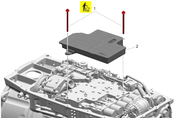
- Automatic Transmission Fluid Filter (2) » Remove — Automatic Transmission Fluid, Fluid Pan and/or Filter Replacement
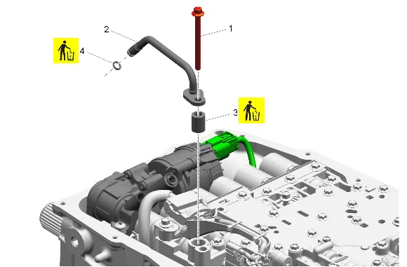
- Control Valve Upper Body Bolt (1) » Remove
- Automatic Transmission Auxiliary Fluid Pump Outlet Pipe (2) » Remove
- Automatic Transmission Auxiliary Fluid Pump Outlet Pipe Seal (3) » Remove and DISCARD
- Automatic Transmission Auxiliary Fluid Pump Seal (4) » Remove and DISCARD
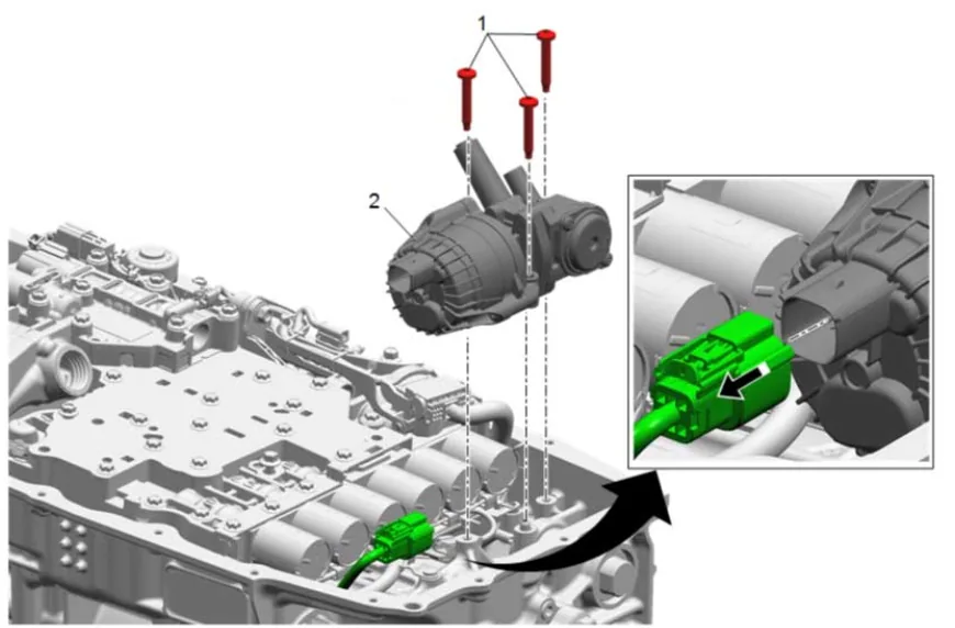
- Automatic Transmission Auxiliary Fluid Pump Bolt (1) » Remove [3x]
- Disconnect the electrical connector.
- Automatic Transmission Auxiliary Fluid Pump (2) » Remove
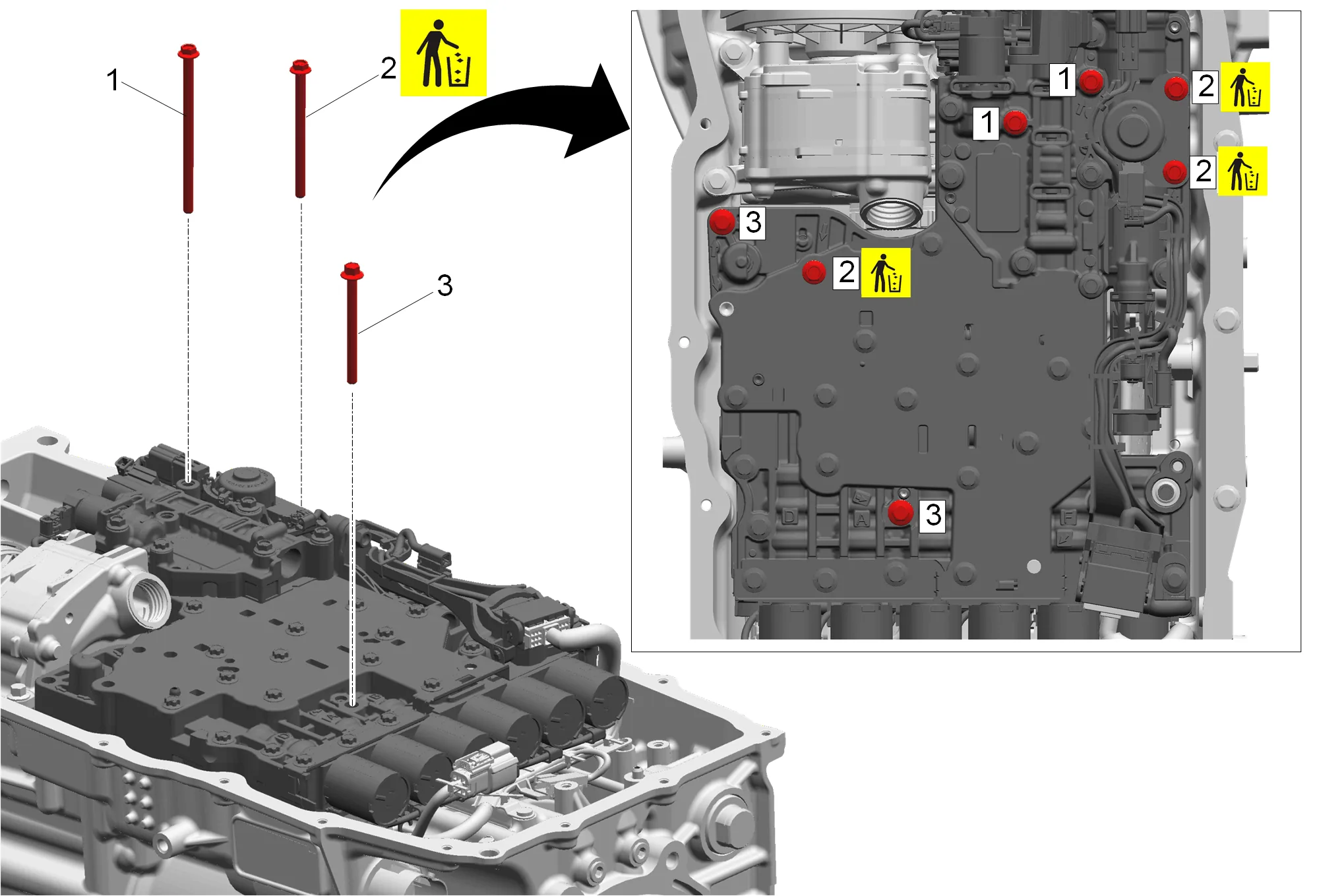
- Control Valve Solenoid Body Bolt (1) » Remove [2x]
- Control Valve Solenoid Body Bolt (2) » Remove and DISCARD [3x]
- Control Valve Solenoid Body Bolt (3) » Remove [2x]
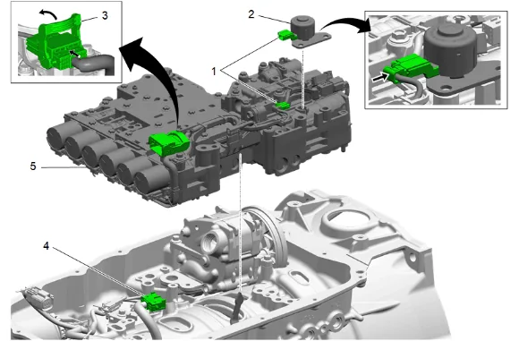
- Disconnect the park inhibitor solenoid electrical connector (1).
- Park Inhibitor Solenoid (2) » Remove
- Unlock the main control wiring harness connector latch (3).
- Disconnect the transmission wiring harness (4).
- Control Valve Body Assembly (5) » Remove
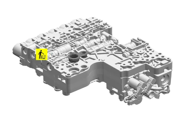
- Automatic Transmission Fluid Pump Seal (1) » Remove and DISCARD
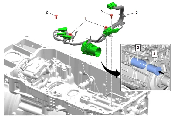
- Automatic Transmission Control Wiring Harness Clip Bracket Bolt (1) » Remove [2x]
- Automatic Transmission Control Wiring Harness Retainer (2) » Remove [2x]
- Install the DT-52089-1 Wiring Harness Pass Through Connector Removal Tool (3) into the DT- 52089-2 Wiring Harness Pass Through Connector Removal Tool then install the DT-52089-1 Wiring Harness Pass Through Connector Removal Tool with the DT-52089-2 Wiring Harness Pass Through Connector Removal Tool onto bulkhead connector.
- Ensure that the DT-52089-1 Wiring Harness Pass Through Connector Removal Tool (3) is pushed all the way on, and flush with the transmission case.
- Push the DT-52089-2 Wiring Harness Pass Through Connector Removal Tool (4) into the DT- 52089-1 Wiring Harness Pass Through Connector Removal Tool (4), and remove the bulkhead connector from the case.
- Disconnect the electrical connectors.
- Automatic Transmission Wiring Harness (6) » Remove
-
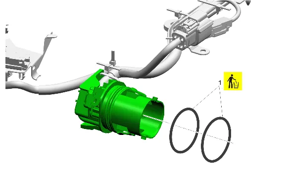
Wiring Harness Connector Seal - O-Ring (1) » Remove and DISCARD [2x] Installation Procedure
-
Wiring Harness Connector Seal - O-Ring (1) » Install NEW [2x]
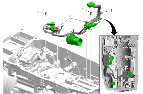
- Automatic Transmission Wiring Harness (1) » Install
- Connect the electrical connectors.
- Position the speed sensor wire under the wire harness retainer tab, install and hand tighten the 2 automatic transmission control wiring harness clip bracket bolts (3).
-
Automatic Transmission Control Wiring Harness Clip Bracket Bolt (4) » Install and tighten [2x] — Fastener Specifications
-
Automatic Transmission Control Wiring Harness Retainer (2) » Install [2x]
-
Connect the transmission wiring harness electrical connectors as necessary.
-
Automatic Transmission Fluid Pump Seal (1) » Install NEW
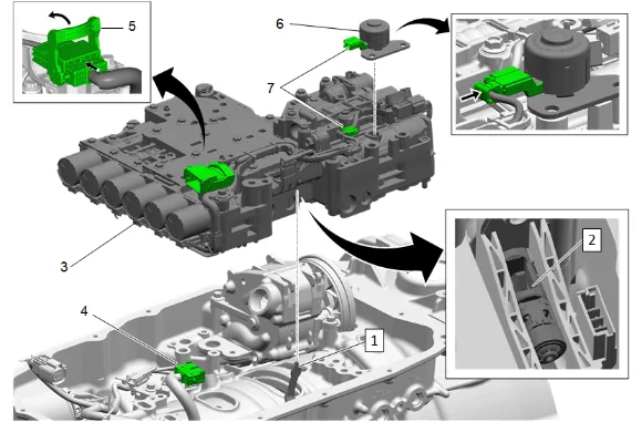
- Place the park pawl actuator (1) in the park position.
- Carefully place the control valve body assembly (3) in the transmission ensuring park pawl actuator lever (1) aligns inside the piston servo opening (2).
- Control Valve Body Assembly (3) » Install
- Connect the main control wiring harness connector (4) then lock the connector latch (5).
- Park Inhibitor Solenoid (6) » Install
- Connect the Park Inhibitor Solenoid connector (7).
- Clean the bolt holes and ensure they are free from old sealant.
- Control Valve Solenoid Body Bolt (1) » Install and tighten in sequence [2x] — Fastener Specifications
- Control Valve Solenoid Body Bolt (2) » Install NEW and tighten in sequence [3x] — Fastener Specifications
- Control Valve Solenoid Body Bolt (3) » Install and tighten in sequence [2x] — Fastener Specifications
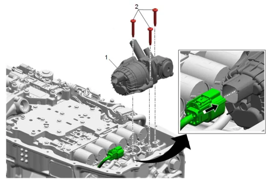
- Automatic Transmission Auxiliary Fluid Pump (1) » Install
- Connect the electrical connector.
- Automatic Transmission Auxiliary Fluid Pump Bolt (2) » Install and tighten [3x] — Fastener Specifications
-
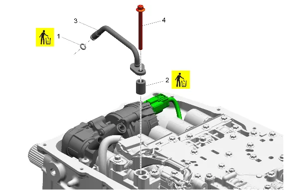
Automatic Transmission Auxiliary Fluid Pump Seal (1) » Install NEW
-
Automatic Transmission Auxiliary Fluid Pump Outlet Pipe Seal (2) » Install NEW
-
Automatic Transmission Auxiliary Fluid Pump Outlet Pipe (3) » Install
-
Control Valve Upper Body Bolt (4) » Install and tighten — Fastener Specifications
-
Automatic Transmission Fluid Filter (2) » Install — Automatic Transmission Fluid, Fluid Pan and/or Filter Replacement
-
Perform the solenoid valve characterization reprogramming procedure. Q77 Transmission Control Solenoid Valve Characterization Programming