Electronic Component Description
B13 Automatic Transmission Fluid Temperature Sensor
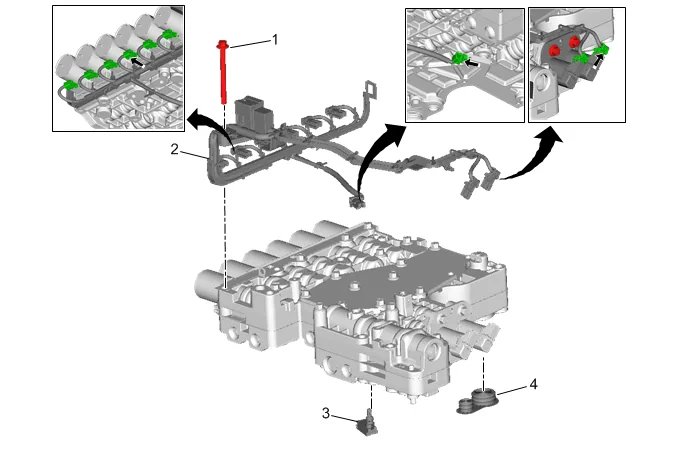
The transmission fluid temperature sensor (3) is a 2 wire negative temperature coefficient thermistor. The TCM supplies a 5 V signal circuit and a low reference circuit to the transmission fluid temperature sensor. The transmission fluid temperature sensor measures the temperature of the fluid in the transmission fluid pan. As the temperature of the fluid increases, the resistance of the sensor decreases, varying the voltage on the signal circuit. The transmission fluid temperature sensor is mounted to the top of the control valve assembly (between the case and the control valve assembly). Automatic Transmission Speed Sensors
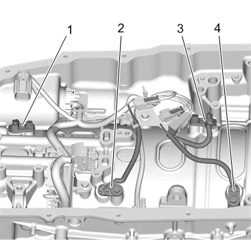
The 10 speed transmission has four speed sensors mounted internally to the transmission case above the valve body:
- B14A Transmission Output Shaft Speed Sensor
- B14DB Transmission Intermediate Speed Sensor 2
- B14C Transmission Input Shaft Speed Sensor
- B14DA Transmission Intermediate Speed Sensor 1 Sensor Type = Two Wire Hall Effect. The TCM has two 9V Reference outputs; 9V1 and 9V2. 9V1 is used for B14C Automatic Transmission Input Speed Sensor , B14DB Automatic Transmission Intermediate Speed Sensor 2 and B315A Transmission Range Control Valve 1 Position Switch . 9V2 is used for B14DA Automatic Transmission Intermediate Speed Sensor 1 , B14A Automatic Transmission Output Speed Sensor and B316 Transmission Park Valve Position Switch . The scan tool displays the input signal as a RPM value. The TCM uses these speed sensor inputs to determine transmission line pressure, shift patterns, correct gear ratio and the torque converter clutch slip speed. B14C Automatic Transmission Input Speed Sensor
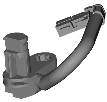
The input speed sensor is also known as the automatic transmission turbine speed sensor. A 40 tooth reluctor ring is splined to the transmission input shaft. B14DA Automatic Transmission Intermediate Speed Sensor 1
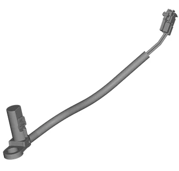
The intermediate speed sensor 1 is also known as the automatic transmission intermediate speed sensor A. A 50 tooth reluctor ring is part of the transmission reaction carrier assembly. B14DB Automatic Transmission Intermediate Speed Sensor 2
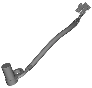
The intermediate speed sensor 2 is also known as the automatic transmission intermediate speed sensor B. A 50 tooth reluctor ring is part of the transmission output carrier shell. B14A Automatic Transmission Output Speed Sensor
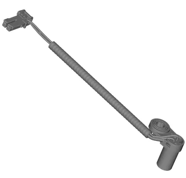
{10L60} A 46 tooth reluctor ring is part of the transmission output carrier assembly, splined to the output shaft. {10L80/90} A 68 tooth reluctor ring is part of the transmission output carrier assembly, splined to the output shaft. { If equipped } G5 Automatic Transmission Auxiliary Fluid Pump / Automatic Transmission Auxiliary Fluid Pump
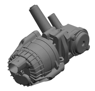
The G5 Transmission Fluid Pump - Electric/Auxiliary is an electric pump used to maintain transmission fluid pressure for autostart/autostop functions. The pump uses 12V DC power and a chassis ground. The pump is commanded on by the TCM when required K71 Transmission Control Module The Transmission Control Module (TCM) for this transmission is a remotely mounted, stand-alone controller. The TCM has one 66 way connector to interface with the vehicle electrical system, transmission assembly and other vehicle control modules. The TCM sends and receives various input and output signals from a number of switches and sensors within the transmission and throughout the vehicle. In addition, the TCM is part of a network of other control modules on the vehicle. This network of control modules will share information with each other over a common serial data communications line. Based upon the TCM software/calibrations and input information the TCM receives, it will always have final authority of when to allow an upshift or downshift whether in manual mode operation or in drive position for automatic shifting. Control Solenoid Valve Body Transmission Control Solenoid Valves The 10 speed transmission could contain a maximum of nine individual solenoids – RPO dependent – installed in various bore locations on the lower control valve body assembly. Eight of the nine solenoid valves are used to control pressure regulation and direction of transmission fluid. The one ON/OFF solenoid valve is only used to direct transmission fluid. The normal operating current range for these solenoid valves is between 0–1.2 amps. If the TCM detects an electrical circuit malfunction or excessive current flow, the TCM will turn OFF the high side driver to that solenoid and set a DTC. The high side driver will reset when the circuit fault is corrected and the ignition switch is cycled. There are three slightly different designed variations of the pressure regulating solenoid valves used on this transmission. They are; linear variable force solenoid, normally low variable force solenoid and normally high variable force solenoid. Normally Low – Linear Solenoids
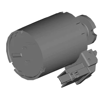
A normally low linear solenoid actuator is an electro-mechanical device that converts electrical power into a mechanical pushing or pulling force or motion. When energized, the solenoid armature applies force to the face of a pressure regulating spool valve. The solenoid actuator applies minimum force with minimum current applied to the solenoid coil. The solenoid actuator applies maximum force with maximum current applied to the solenoid coil. Transmission control solenoid valves 1, 2, 3, 4, 5 & 6 are of the linear design. Normally Low – Variable Force Solenoid
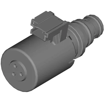
A normally low variable force solenoid is an electro-mechanically operated valve. The valve is controlled by an electric current through the solenoid coil. The solenoid valve varies the control pressure depending on the current applied to the solenoid coil. The solenoid valve control pressure is low with no or minimum current applied to the solenoid coil. The solenoid valve control pressure increases with increasing current applied to the solenoid coil. Nominal resistance of a variable force solenoid is 5.1 Ohms +/- 0.3 Ohms @ 20C (68F). As the temperature of the solenoid windings increase, the resistance will also increase. When the solenoid temperature is at 100C (212F), the resistance value will be approximately 6.7 Ohms +/- 0.4 Ohms. Transmission control solenoid valve 8 is a normally low solenoid. Normally High – Variable Force Solenoid
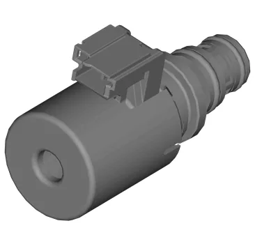
A normally high variable force solenoid is an electro-mechanically operated valve. The valve is controlled by an electric current through the solenoid coil. The solenoid valve varies the control pressure depending on the current applied to the solenoid coil. The solenoid valve control pressure is high with no or minimum current applied to the solenoid coil. The solenoid valve control pressure decreases with increasing current applied to solenoid coil. Nominal resistance of a variable force solenoid is 5.1 Ohms +/- 0.3 Ohms @ 20C (68F). As the temperature of the solenoid windings increase, the resistance will also increase. When the solenoid temperature is at 100C (212F), the resistance value will be approximately 6.7 Ohms +/- 0.4 Ohms. Transmission control solenoid valve 7 is a normally high solenoid. ON/OFF Solenoid
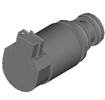
The ON/OFF solenoid valve is an electro-mechanically operated valve. The valve is controlled by an electric current through the solenoid coil. This solenoid is normally closed solenoid that is controlled ON (fully open) or OFF (fully closed). Nominal resistance of an On/Off solenoid is 18–22 Ohms @ 20C (68F). As the temperature of the solenoid windings increase, the resistance will also increase. When the solenoid temperature is at 100C (212F), the resistance value will be approximately 26–31 Ohms. Transmission control solenoid valve 9 is an ON/OFF solenoid. Solenoid Characterization Transmission control solenoid valves 1–8 are pressure regulating valves. Each solenoid valve is tested after assembly to determine the output fluid pressure at certain electrical values, applied to the coil winding. This information is referred to as solenoid current/pressure data points. The solenoid valves are tested two ways, with an increasing and then a decreasing electrical current applied to the coil winding. The resultant current versus pressure data points are saved and assigned a file number. This file number is marked on the solenoid valve housing end or on the valve body itself. The solenoid performance data file is stored on the TIS web site. This data file is programmed and stored in the vehicle’s TCM. Replacing any of the following components will require the TCM to be programmed with either the new or existing solenoid valve performance data, depending on what component is replaced. Transmission assembly – program the TCM with the new data file stored on the TIS web site for all pressure regulating solenoid valves. Lower control valve body assembly with solenoid valves — program the TCM with the new data file stored on the TIS web site for all pressure regulating solenoid valves. Transmission Control Module — program the TCM with the existing data file stored on the TIS web site for all pressure regulating solenoid valves. One or more solenoids — program the TCM with the new data file stored on the TIS web site for all pressure regulating solenoid valves that were replaced. Electronic Transmission Range Select (ETRS) Componenents B315A Transmission Range Control Valve 1 Position Switch
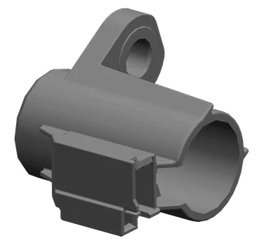
This position switch uses the 9V1 reference voltage from the TCM to power the component. This component detects the position of the component: ETRS Valve B316 Transmission Park Valve Position Switch
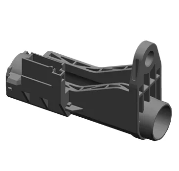
This position switch uses the 9V2 reference voltage from the TCM to power the component. This component detects the position of the component: Park Servo Valve M123 Transmission Park Valve Lock Solenoid Actuator
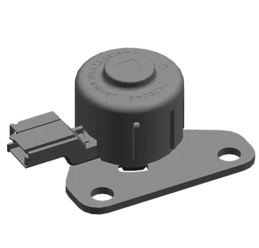
When energized the actuator will extend a pin, locking the park servo in the applied position which holds the parking pawl in the out of park position. The M123 Transmission Park Valve Lock Solenoid Actuator is also known as the: – Park Inhibit Solenoid – Park Inhibitor Solenoid – Park Inhibit Solenoid Actuator (PISA) Automatic Transmission Wiring Harness
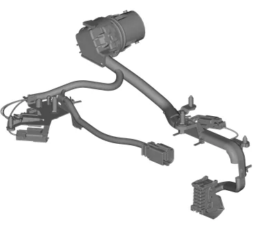
There are three separate internal wire harness assemblies. (PASS-THRU) or (5) (MAIN/SOLENOID) or (305) (JUMPER) or (371) The transmission internal wire harness is serviced by replacement only. No repairs to the internal wire harness should be attempted.