Battery Electrical Drain_Parasitic Load Test
Battery Electrical Drain/Parasitic Load Test 12 V Battery The following procedure is for the 12 V battery only. Diagnostic Instructions Perform the Diagnostic System Check - Vehicle prior to using this diagnostic procedure. Review Strategy Based Diagnosis for an overview of the diagnostic approach. Diagnostic Procedure Instructions provides an overview of each diagnostic category. Circuit/System Description Components most likely to cause a parasitic draw on the vehicles battery are switches, relays, and control modules. After the ignition is turned OFF the control modules will begin to go to sleep (shut OFF). All control modules do not go to sleep at the same time, some may take up to 30 minutes or longer after turning the ignition off before going to sleep e.g. RAP or IRAP. Other components such as EVAP, HVAC afterblow, EV Battery Heater/Coolers, OnStar and keyless entry control modules (approach detection in keyless access vehicles) etc. may periodically wake up then go back to sleep. These are all normal conditions, use of a DMM set to Min/Max may help identify the normal types of spikes in the parasitic draws . Diagnostic Aids Active Draws If the battery voltage is interrupted by removing fuses, relays, module or component connectors, or disconnecting the battery may cause the condition to clear or reset. To prevent a loss of power when disconnecting the battery install the EQPMSK6211 Battery Booster Pack or equivalent to the positive and negative battery cables prior disconnecting it to prevent a loss of voltage. Verify no aftermarket accessories are installed or connected to the Auxiliary Power Ports, Audio Ports, or DLC. e.g. insurance snapshot or tracking devices. On Some Vehicles the Auxiliary Power Ports can have B+ at all times (not controlled by RAP) by relocating the fuse in the fuseblock. Aftermarket accessories installed into the courtesy lamp circuit may cause the inadvertent power timer in the K9 Body Control Module (BCM) to keep resetting. This may cause the BCM to remain awake and cause a current drain on the battery. Verify that the battery and charging system are operating correctly. Refer to Battery Charging and Charging System Test. An engine off natural vacuum evaporative test can occur if the Engine Control Module (ECM) determines the drive cycle has met the appropriate criteria immediately after key off. The ECM will stay awake and the vent solenoid will stay energized for up to 45 min. The typical current draw for this is approximately 1 A. The K9 Body Control Module has discrete input and output terminals to control the vehicle’s body functions. The K9 Body Control Module is wired to the High Speed GMLAN bus, Low Speed GMLAN bus and multiple Local Interconnect Network (LIN) buses and acts as a gateway between them. The various K9 Body Control Module input and output circuits are illustrated in the corresponding functional areas on the K9 Body Control Module electrical schematics. The K9 Body Control Module functions as the power mode master. The ignition switch is a low current switch with multiple discrete ignition switch signals to the power mode master for determining the power mode that will be sent over the serial data circuits to the other devices that need this information; the power mode master will activate relays and other direct outputs of the power mode master as needed. Refer to Power Mode Description and Operation for a complete description of power mode functions. The K9 Body Control Module functions as a gateway or translator. The purpose of the gateway is to translate serial data messages between the High Speed GMLAN bus and the Low Speed GMLAN bus for communication between the various devices. The gateway will interact with each network according to that network’s transmission protocol. All communication between the K9 Body Control Module and a scan tool is done through the primary High Speed GMLAN bus. Generation 5 and prior OnStar module does can “wake up” every 10 minutes for the first 48 hours, for Generation 6 and later the current draw is very low, less than 40 mA, the OnStar system is left in that state for up to the first 48 h. a parasitic draw of up to 40 mA with an occasional spike as high as 80 mA for the first 48 hours is normal. Refer to OnStar Description and Operation OnStar Sleep Cycle. Some automatic climate control systems can remain in a semi awake state for up to three hours, actual draw amounts vary by vehicle platform but are typically not greater than 50 mA. An extremely low mA current level is consumed by the body control module for monitoring purposes, actual system wake up occurs when the fobs for the vehicle are activated or approach is detected on keyless access vehicles. Other devices that operate on the same remote keyless entry frequency, such as the tire pressure monitoring sensors and other vehicle Fobs in the vicinity, may cause the body control module to have a 100 mA spike. These spikes are normal and occur too briefly to have a significant effect on battery drain. If an excessive current draw is not present during initial testing, continue periodic testing over a 1–2 hour period to see if the current draw increases and stays above an unacceptable level.
| Current Drain | Days |
|---|
| Current Drain | Days |
|---|
Intermittent Draws The Battery Draw Customer Verification Worksheet may be helpful isolating or duplicating the customers concern CCVS - Battery Draw When diagnosing an intermittent battery draw, if the battery voltage is interrupted by removing fuses, relays, module or component connectors, or disconnecting the battery may cause the condition to clear or reset. To prevent a loss of power when disconnecting the battery install the EQPMSK6211 Battery Booster Pack or equivalent to the positive and negative battery cables prior disconnecting it to prevent a loss of voltage. Verify no aftermarket accessories are installed or connected to the Auxiliary Power Ports, Audio Ports, or DLC. e.g. insurance snapshot or tracking devices. On Some Vehicles the Auxiliary Power Ports can have B+ at all times (not controlled by RAP) by relocating the fuse in the fuseblock. Rule out customer driving habits such as regular short trips that do not allow enough time to properly charge the battery. Refer to Battery Description and Operation. Verify that the battery and charging system are operating correctly. Refer to Battery Charging and Charging System Test. A battery discharging for no apparent reason while the vehicle is parked can be caused by an intermittent draw, such as a module waking up, or a continuous draw, such as a dome light or stuck relay. An engine off natural vacuum evaporative test can occur if the Engine Control Module (ECM) determines the drive cycle has met the appropriate criteria immediately after key off. The ECM will stay awake and the vent solenoid will stay energized for up to 45 min. The typical current draw for this is approximately 1 A. The K9 Body Control Module has discrete input and output terminals to control the vehicle’s body functions. The K9 Body Control Module is wired to the High Speed GMLAN bus, Low Speed GMLAN bus and multiple Local Interconnect Network (LIN) buses and acts as a gateway between them. The various K9 Body Control Module input and output circuits are illustrated in the corresponding functional areas on the K9 Body Control Module electrical schematics. The K9 Body Control Module functions as the power mode master. The ignition switch is a low current switch with multiple discrete ignition switch signals to the power mode master for determining the power mode that will be sent over the serial data circuits to the other devices that need this information; the power mode master will activate relays and other direct outputs of the power mode master as needed. Refer to Power Mode Description and Operation for a complete description of power mode functions. The K9 Body Control Module functions as a gateway or translator. The purpose of the gateway is to translate serial data messages between the High Speed GMLAN bus and the Low Speed GMLAN bus for communication between the various devices. The gateway will interact with each network according to that network’s transmission protocol. All communication between the K9 Body Control Module and a scan tool is done through the primary High Speed GMLAN bus. Generation 5 and prior OnStar module does can “wake up” every 10 minutes for the first 48 hours, for Generation 6 and later the current draw is very low, less than 40 mA, the OnStar system is left in that state for up to the first 48 h. a parasitic draw of up to 40 mA with an occasional spike as high as 80 mA for the first 48 hours is normal. Refer to OnStar Description and Operation OnStar Sleep Cycle. Some automatic climate control systems can remain in a semi awake state for up to three hours, actual draw amounts vary by vehicle platform but are typically not greater than 50 mA. An extremely low mA current level is consumed by the body control module for monitoring purposes, actual system wake up occurs when the fobs for the vehicle are activated or approach is detected on keyless access vehicles. Other devices that operate on the same remote keyless entry frequency, such as the tire pressure monitoring sensors and other vehicle Fobs in the vicinity, may cause the body control module to have a 100 mA spike. These spikes are normal and occur too briefly to have a significant effect on battery drain. If an excessive current draw is not present during initial testing, continue periodic testing over a 1–2 hour period to see if the current draw increases and stays above an unacceptable level.
| Current Drain | Days |
|---|
Reference Information Schematic Reference Control Module References Connector End View Reference Master Electrical Component List Electrical Information Reference Circuit Testing Testing for Intermittent Conditions and Poor Connections Connector Repairs Wiring Repairs Scan Tool Reference Control Module References for scan tool information Special Tools EL 38758 Parasitic Draw Test Switch For equivalent regional tools, refer to Special Tools. Circuit/System Verification
- Verify meter operating correctly, refer to the tools owner manual for tool being used,
- Road test the vehicle in the same manner as the customer does, based on information obtained from the customer verification sheet.
- Activate all the accessories the vehicle is equipped with, such as the radio, rear seat entertainment, rear defogger, windows, sunroof, front and rear HVAC etc. (operate components through a full cycle) confirm everything is operating correctly and note any components that are not operating correctly.
- Connect a 50 Amp inductive amp clamp to the negative battery cable that can read down to 1 mA.
- Ignition OFF.
- Ignition off, exit the vehicle following the same manner that the customer does, based on information obtained from the customer verification sheet. CCVS - Battery Draw
- Allow all modules and components to go to sleep.
- Verify there is less than 40 mA of parasitic current drain. ⇒ If greater than the specified range, refer to Circuit/System Testing. ⇓ If less than the specified range
- The condition may be an intermittent fault and is currently not present. Perform additional road test or repeat customer scenario to attempt to duplicate the draw Alternate Method for Vehicles with Battery Sensor Module
- Verify meter operating correctly, refer to the tools owner manual for tool being used,
- Connect the EQPMSK6211 Battery Booster Pack or equivalent to the Battery positive and negative jump start posts prior to disconnecting the negative battery cable to prevent a loss of voltage which could reset or clear an intermittent draw.
- Allow all modules and components to go to sleep.
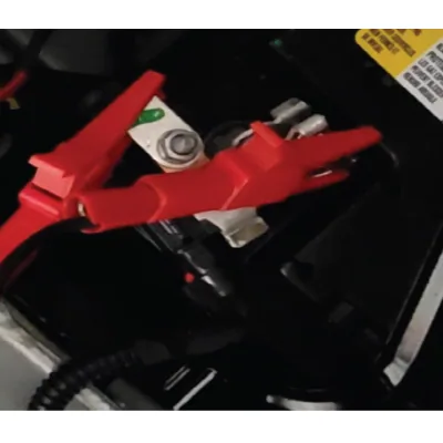
- Connect a 10 A fused jumper wire between the Battery Negative post clamp and the other end of the Negative Battery Cable.
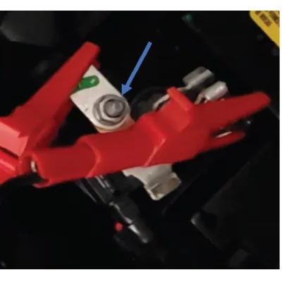
- Remove the Current sensor stud nut and remove the negative cable from the Battery Sensor Module.
- Check the fuse in the jumper wire. The fuse should be OK. ⇒ If the jumper wire fuse is blown, the vehicle has an Active excessive parasitic draw. Refer to Circuit/System Testing ⇓ If the jumper wire fuse is not blown,
- Disconnect the the EQPMSK6211 Battery Booster Pack or equivalent
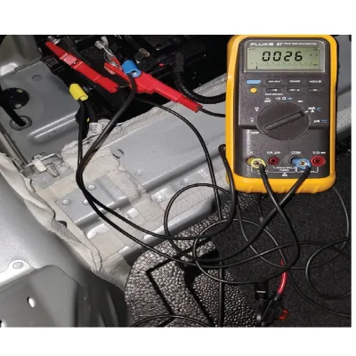
- Verify there is less than 40 mA of parasitic current drain. ⇒ If greater than the specified range, refer to Circuit/System Testing. ⇓ If less than the specified range
- Reconnect the Battery Negative Battery Cable to the Battery Sensor Module.
- Road test the vehicle in the same manner as the customer does, based on information obtained from the customer verification sheet. CCVS - Battery Draw
- Activate all the accessories the vehicle is equipped with, such as the radio, rear seat entertainment, rear defogger, windows, sunroof, front and rear HVAC etc. (operate components through a full cycle) confirm everything is operating correctly and note any components that are not operating correctly.
- Ignition off, exit the vehicle following the same manner that the customer does, based on information obtained from the customer verification sheet.
- Connect the EQPMSK6211 Battery Booster Pack or equivalent to the Battery positive and negative jump start posts prior to disconnecting the negative battery cable to prevent a loss of voltage which could reset or clear an intermittent draw.
-
Allow all modules and components to go to sleep.
-
Connect a 10 A fused jumper wire between the Battery Negative post clamp and the other end of the Negative Battery Cable.
-
Remove the Current sensor stud nut and remove the negative cable from the Battery Sensor Module.
-
Check the fuse in the jumper wire. The fuse should be OK. ⇒ If the jumper wire fuse is blown, the vehicle has an Active excessive parasitic draw. Refer to Circuit/System Testing ⇓ If the jumper wire fuse is not blown,
-
Disconnect the the EQPMSK6211 Battery Booster Pack or equivalent
-
Verify there is less than 40 mA of parasitic current drain. ⇒ If greater than the specified range, refer to Circuit/System Testing. ⇓ If less than the specified range
-
The condition may be an intermittent fault and is currently not present. Perform additional road test, repeat customer scenario per the Battery Draw customer verification sheet to attempt to duplicate the draw. Alternate Method for Vehicles without a Battery Sensor Module Using the EL 38758 Parasitic Draw Test Switch
- Verify meter operating correctly, refer to the tools owner manual for tool being used,
- Connect the EQPMSK6211 Battery Booster Pack or equivalent to the Battery positive and negative jump start posts prior to disconnecting the negative battery cable to prevent a loss of voltage which could reset or clear an intermittent draw.
- Ignition OFF, disconnect the battery negative cable from the battery. Refer to Battery Negative Cable Disconnection and Connection.
- Turn the EL 38758 switch knob to the OFF position.
- Install the male end of the EL 38758 switch to the battery ground terminal.
- Install the battery negative cable to the female end of the EL 38758 switch.
- Turn the EL 38758 switch knob to the ON position.
- Disconnect the EQPMSK6211 Battery Booster Pack or equivalent.
- Allow all modules and components to go to sleep.
- Connect a 10 A fused jumper wire to the test switch tool terminals.
- Turn the EL 38758 switch knob to the OFF position. The current now flows through the jumper wire.
- Check the fuse in the jumper wire. The fuse should be OK. ⇒ If the jumper wire fuse is blown, the vehicle has an Active excessive parasitic draw. Refer to Circuit/System Testing ⇓ If the jumper wire fuse is not blown,
- Turn the EL 38758 switch knob to the ON position. Remove the fused jumper wire.
- Connect a DMM set to the 10 A DC scale between the test switch tool terminals.
- Turn the EL 38758 switch knob to the OFF position. The current now flows through the DMM.
- Verify there is less than 40 mA of parasitic current drain. ⇒ If greater than the specified range, refer to Circuit/System Testing. ⇓ If less than the specified range
- Turn the EL 38758 switch knob to the OFF position.
- Road test the vehicle in the same manner as the customer does, based on information obtained from the customer verification sheet. CCVS - Battery Draw
- Activate all the accessories the vehicle is equipped with, such as the radio, rear seat entertainment, rear defogger, windows, sunroof, front and rear HVAC etc. (operate components through a full cycle) confirm everything is operating correctly and note any components that are not operating correctly.
- Ignition off, exit the vehicle following the same manner that the customer does, based on information obtained from the customer verification sheet.
- Allow all modules and components to go to sleep.
- Connect a 10 A fused jumper wire to the test switch tool terminals.
- Turn the EL 38758 switch knob to the OFF position. The current now flows through the jumper wire.
- Check the fuse in the jumper wire. The fuse should be OK. ⇒ If the jumper wire fuse is blown, refer to Circuit/System Testing. ⇓ If the jumper wire fuse is not blown,
- Turn the EL 38758 switch knob to the ON position. Remove the fused jumper wire.
- Connect a DMM set to the 10 A DC scale between the test switch tool terminals.
- Turn the EL 38758 switch knob to the OFF position. The current now flows through the DMM.
- Verify there is less than 40 mA of parasitic current drain. ⇒ If greater than the specified range, refer to Circuit/System Testing. ⇓ If less than the specified range
- The condition may be an intermittent fault and is currently not present. Perform additional road test, repeat customer scenario per the Battery Draw customer verification sheet to attempt to duplicate the draw. Circuit/System Testing
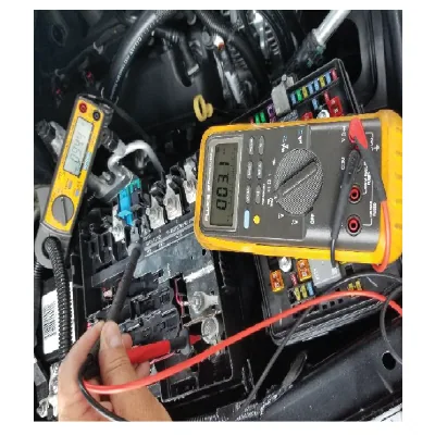
Battery Junction Block Voltage Drop Example
- If the equipped with a battery Junction block and if it is accessible, utilize and inductive amp clamp or perform a voltage drop test between the battery positive post and each leg of the battery junction block to help determine which fuse block is containing the draw. ⇒ If a Parasitic Draw has not been isolated in Step 1.
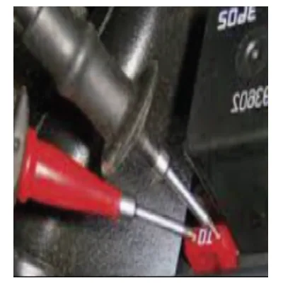
Standard Fuse Voltage Drop Test Example
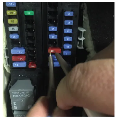
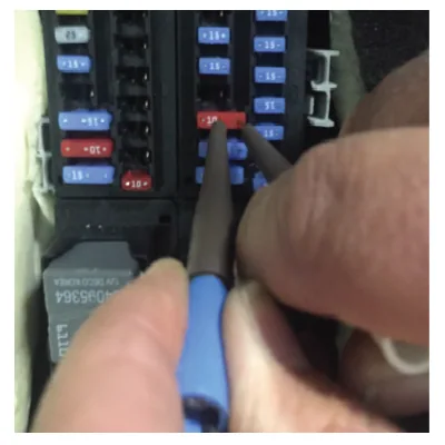
Standard Fuse Voltage Drop Test Example
- Verify an excessive current draw is not present by removing each remaining J-Case fuse(s), circuit breaker(s), relay(s), components and modules one at a time while monitoring the draw to verify it drops to below 40 mA. ⇒ If an excessive parasitic draw is found
- The condition may be an intermittent fault and is currently not present. Stuck switch Stuck relay Control module Perform additional road test, repeat customer scenario per the Battery Draw customer verification sheet to attempt to duplicate the draw, Repair Instructions Perform the Diagnostic Repair Verification after completing the repair. Control Module References for control module replacement, programming and setup