Fuel System Description (1)
Engine Controls and Fuel - 3.0L LM2 Diesel | Description and Operation | Document ID: 5702169 Fuel System Description
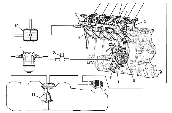
- Fuel Filter Assembly
- B47 Fuel Pressure Sensor
- B47B Fuel Rail Pressure Sensor
- Q18B Fuel Pressure Regulator 2
- Q17 Fuel Injector
- G18 High Pressure Fuel Pump
- Q18A Fuel Pressure Regulator 1
- Q18C Fuel Pressure Regulator 3
- E12 Glow Plug
- K20 Engine Control Module
- A7 Fuel Pump and Level Sensor Assembly
- Fuel Cooler The primary fuel tank stores the fuel supply. The primary fuel tank contains a 3–phase electric fuel pump that is controlled by the fuel pump driver control module and engine control module. Fuel is pumped from the primary fuel tank through the fuel feed line to the fuel filter assembly. The fuel filter assembly consists of a fuel filter/water separator, fuel heater, fuel temperature sensor, and a water in fuel sensor. Fuel flows out of the fuel filter assembly through the rear fuel feed pipe and past the fuel pressure sensor to the high pressure fuel pump. High pressure fuel is supplied through the high pressure fuel line to the fuel rail and then through the fuel injector lines to the fuel injectors. High pressure fuel is controlled by the ECM, fuel pressure regulators 1,2, and 3. Excess fuel returns to the fuel tank through the fuel return pipes. Fuel Cooler Fuel Cooler The fuel cooler is located under the vehicle. The returning fuel goes through the fuel cooler prior to reaching the vehicle’s fuel tank. Coolant from the engines cooling system flows through the fuel cooler in order to cool the fuel and maintain a constant fuel temperature. Fuel Feed and Return Pipes The fuel feed pipe carries fuel from the fuel tank to the fuel filter/heater, exhaust aftertreatment fuel injector, and fuel injection pump. The fuel return pipe carries fuel from the fuel rail assemblies back to the fuel tank. Fuel Fill Cap Fuel Fill Cap (if equipped) The fuel fill cap is equipped with a seal and a vacuum relief valve and is tethered. A torque- limiting device prevents the cap from being over tightened. To install the cap, turn the cap clockwise until you hear clicks. This indicates that the cap is correctly torqued and fully seated. A built-in device indicates that the fuel filler cap is fully seated. A fuel filler cap that is not fully seated may cause a malfunction in the emission system. Capless Fuel Fill (if equipped) Some vehicles may have a capless fuel fill design behind a locking fuel door. There is no fuel fill cap to remove. One just fully inserts the fuel nozzle into the fill neck, making sure it latches before refueling. Flapper valves close to seal this interface once the fill nozzle is removed. Fuel Filter Assembly The fuel filter assembly is located near the left frame rail and contains the following components: Fuel Filter/Water Separator Fuel Heater Fuel Temperature Sensor Water in Fuel Sensor Fuel Filter/Water Separator The paper filter element traps particles in the fuel that may damage the fuel injection system and is designed to allow trapped water particles to settle to the bottom of the filter assembly. Fuel Heater The fuel heater is controlled by the engine control module (ECM). When the temperature of the fuel is below the calibrated level the ECM will command the fuel heater relay On. When the relay is On, battery voltage is supplied to the fuel heater to assist in cold weather operation. Fuel Temperature Sensor The fuel temperature sensor is a thermistor that is located in the fuel filter assembly. The ECM monitors the fuel temperature sensor through the fuel pump driver control module in order to calculate the temperature of the fuel entering the fuel injection pump. Water in Fuel Sensor The water in fuel sensor is a sensor that monitors for the presence of diesel fuel and water. When water is present the fuel pump driver control module detects low voltage on the signal circuit and sends a message to the ECM. The ECM sends a serial data message to the instrument panel cluster to display the WATER IN FUEL SERVICE REQUIRED message. Fuel Injectors Fuel Injectors The fuel injector is a solenoid device that is supplied a high voltage supply circuit and a high voltage control circuit from the ECM. Electrical pulses are supplied by the ECM to each fuel injector at the correct time and sequence determined by information received from the camshaft position sensor. When the fuel injector receives electrical pulses, fuel is sprayed from the fuel injector tip directly into the combustion chamber on the compression stroke of the engine. The fuel injectors are located above each cylinder and deliver fuel directly into the cylinder. Each injector has a high pressure fuel pipe from the fuel rail and a return line. Fuel Injection Quantity In the calibration / controls community this diagnostic is referred to as the Fuel Setpoint Adaptation (FSA). This algorithm is used to estimate the actual injected fuel quantity. The goal of FSA is to account for injectors that drift during the lifetime of the vehicle. The algorithm estimates the real injected fuel quantity by using input from the mass airflow (MAF) sensor & nitrogen oxides (NOx) sensor 1 to determine the air/fuel ratio. If airflow parameters are incorrect due to leaks, blockages, malfunctioning EGR, inaccurate MAF sensor/NOx sensor 1 signals, or fuel injectors that are not performing as intended, a skewed air-fuel ratio could negatively affect the FSA. Fuel Injection Timing The engine control module (ECM) has the ability to learn injector timing performance. When the engine is at operating temperature, throttle closed and in deceleration fuel cut-off mode, the ECM will pulse each injector individually and measure the changes in rotational speed of the crankshaft using the input from the crankshaft position sensor. The ECM will run this diagnostic at one fuel rail pressure operating point for each injector. The ECM stores the injector timing value. Fuel Pipe O-Rings O-rings seal the connections in the fuel system. Fuel system O-ring seals are made of special material. Service the O-ring seals with the correct service part. Fuel Pressure Regulator 1 & 3 The engine control module (ECM) controls the fuel rail pressure using three pulse width modulated fuel rail pressure regulators. Fuel pressure regulator 1 & 3 are located in the fuel injection pump and meters the amount of fuel that enters the high pressure side of the pump. From the high pressure pump, the fuel moves to the fuel rail through high pressure steel lines. The fuel rail distributes high pressure fuel to all 6 fuel injectors. Fuel rail pressure is controlled by fuel pressure regulator 1 & 3 when fuel temperature is warmer than 8°C (46.4°F) and the accelerator pedal is at a steady state, during a tip-in, or accelerating. Fuel Pressure Regulator 2 The engine control module (ECM) controls the fuel rail pressure using 3 pulse width modulated fuel rail pressure regulators. Fuel pressure regulator 2 is located on the rear of the fuel rail and meters the amount of fuel being returned to the fuel tank. The ECM varies the pulse width modulated voltage to fuel pressure regulator 2 to relieve excessive fuel pressure allowing fuel to return to the fuel tank. When the ignition is Off, fuel pressure regulator 2 opens to bleed off the pressure on the high pressure side of the fuel system. Fuel rail pressure is controlled by fuel pressure regulator 2 when the fuel temperature is colder than 8°C (46.4°F) or during accelerator pedal tip-out. Fuel Pressure Sensor The fuel pressure sensor is located in the fuel feed pipe. The fuel pressure sensor monitors the fuel pressure in the fuel line. The fuel pump driver control module monitors the voltage signal from the fuel pressure sensor and sends serial data to the ECM in order to provide low side fuel pressure control. Fuel Rail Assembly The fuel rail attaches to the cylinder head. The fuel rail distributes pressurized fuel to the fuel injectors through the fuel lines. Fuel Rail Pressure Sensor The fuel rail pressure sensor is a dual analog sensor that provides two fuel rail pressure signals to the engine control module (ECM) and is located in the end of the fuel rail assembly. The ECM provides a 5 V reference voltage on the 5 V reference circuit and ground on the low reference circuit. The ECM receives a varying signal voltage on both the fuel rail pressure sensor and fuel rail pressure sensor 2 signal circuits. The ECM monitors the voltage on both of the fuel rail pressure sensor circuits and compares the values to determine if the sensors are accurate. When the fuel pressure is high, the fuel rail pressure sensor signal voltage is high and the fuel rail pressure sensor 2 signal voltage is low. When the fuel pressure is low, the fuel rail pressure sensor signal voltage is low and the fuel rail pressure sensor 2 signal voltage is high. Fuel Tank The fuel tank store the fuel supply. The primary fuel tank is located on the left side of the vehicle and vehicles equipped with dual fuel tanks, the secondary fuel tank is located in the rear of the vehicle. The fuel tanks are each held in place by 2 metal straps that attach to the frame. The fuel tanks are molded from high density polyethylene. Fuel Tank Fuel Pump Module The fuel tank fuel pump module is located inside of the fuel tank. The fuel tank module consists of the following major components: The fuel level sensor The fuel pump and reservoir assembly The fuel strainer Fuel Level Sensor The fuel level sensor consists of a float, a wire float arm, and a ceramic resistor card. The position of the float arm indicates the fuel level. The fuel level sensor contains a variable resistor which changes resistance in correspondence with the position of the float arm. The Fuel Pump Power Control Module sends the fuel level information via high speed CAN–bus to the engine control module (ECM). The ECM then sends the fuel level percentage via low speed CAN–bus to the instrument panel cluster (IPC) in order to control the fuel gauge. The control module monitors the signal circuit of the fuel level sensor in order to determine the fuel level. Fuel Pump The fuel pump is mounted in the primary fuel tank module reservoir. The engine control module (ECM) supplies voltage to the fuel pump driver control module for 30 s when the ignition is turned on and continuously when the engine is running. While this voltage is being received, the ECM sends a serial data signal to the fuel pump driver control module containing the desired fuel pump speed. The fuel pump driver control module actuates the brushless fuel pump by means of a three phase signal and controls the fuel pump speed according to serial data signals received from the ECM containing the desired fuel pump speed. During a cold start, in order to warm the fuel the high pressure pump operates at full output and the pressure in the rail is regulated by fuel pressure regulator 2. This mode is also active during fuel injection cut-off. When in this mode, the fuel return line can flow up to 230 l/h (60.8 g/h). Fuel Strainer The fuel strainer attaches to the lower end of the fuel tank fuel pump module. The fuel strainer is made of woven plastic. The functions of the fuel strainer are to filter contaminants and to wick fuel. The fuel strainer is self-cleaning and normally requires no maintenance. Fuel stoppage at this point indicates that the fuel tank contains an abnormal amount of sediment. High Pressure Fuel Pump The high pressure fuel pump is a mechanical pump and is attached to the lower drivers side of the engine block. The high pressure fuel pumps provides high pressure fuel to the fuel rail at a specified pressure regulated by the fuel pressure regulators. Quick-Connect Fittings Quick-connect fittings provide a simplified means of installing and connecting fuel system components. The fittings consist of a unique female connector and a compatible male pipe end. O- rings, located inside the female connector, provide the fuel seal. Integral locking tabs inside the female connector hold the fittings together.