Instrument Panel Upper Trim Panel Replacement
Single Use Fasteners and Components Instrument Panel Airbag Removal Procedure
- Disable the SIR system. SIR Disabling and Enabling
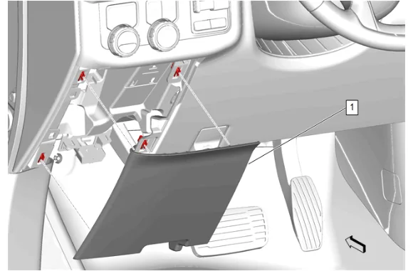
- Instrument Panel Lower Trim Panel Outer Filler (1) » Remove
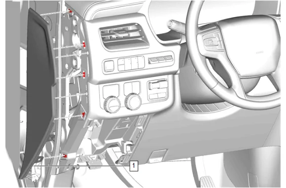
- Using a flat-bladed plastic trim tool, release the retaining clips.
- Instrument Panel Fuse Block Access Hole Cover (1) » Remove
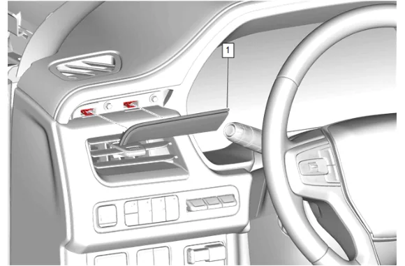
- Using a flat-bladed plastic trim tool, release the retaining clips.
- Instrument Panel Trim Plate Applique (1) » Remove
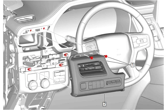
- Instrument Panel Trim Pad Bolt (1) » Remove [2x]
- Instrument Panel Trim Pad (2) » Remove
- Disconnect the electrical connectors.
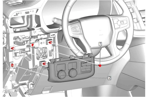
- Instrument Panel Switch Trim Plate Bolt (1) » Remove
- Disconnect the electrical connectors.
- Instrument Panel Switch Trim Plate (2) » Remove
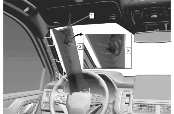
- Reposition the weatherstrip as necessary.
- Pull down the windshield garnish molding (1) rearwards to release the tether from the A pillar.
- Access the windshield garnish bolt (2) which is located on the backside of the windshield garnish molding (1) and secures the tether to the A pillar.
- Windshield Garnish Molding Bolt (2) » Remove
- Windshield Garnish Molding (1) » Remove
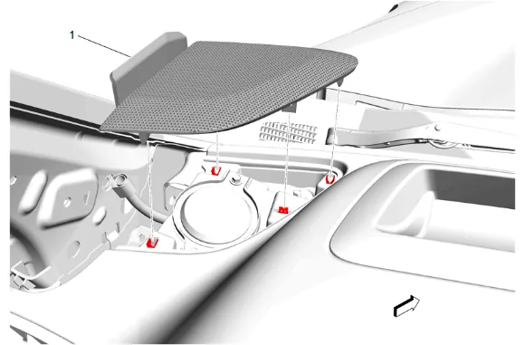
- Using a flat-bladed plastic trim tool, release the retaining clips.
- Radio Front Speaker Grille (1) » Remove
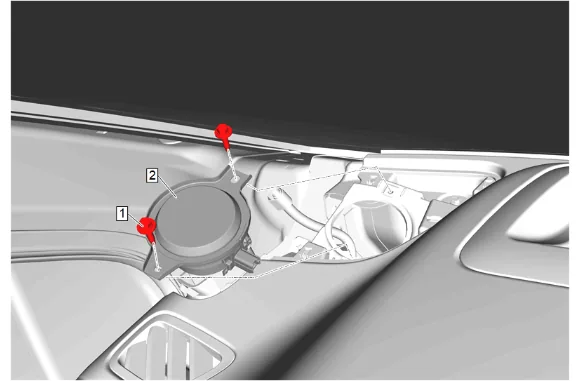
- Radio Front Speaker Bolt (1) » Remove [2x]
- Radio Front Speaker (2) » Remove
- Disconnect the electrical connector.
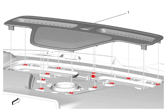
- Using a flat-bladed plastic trim tool, release the retaining clips.
- Disconnect the electrical connector.
- Instrument Panel Extension (1) » Remove
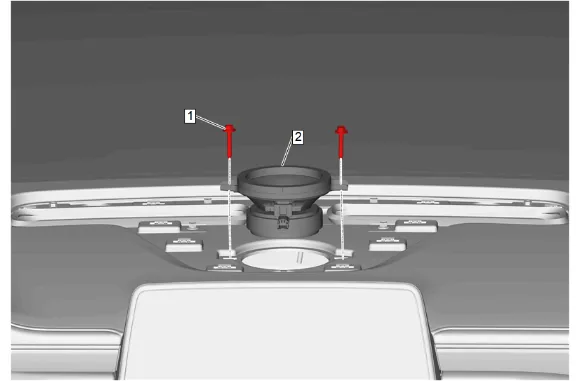
- Radio Front Center Speaker Bolt (1) » Remove [2x]
- Radio Front Center Speaker (2) » Remove
- Disconnect the electrical connector.
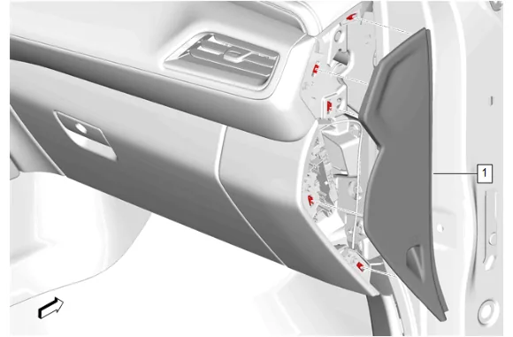
- Using a flat-bladed plastic trim tool, release the retaining clips.
- Instrument Panel Fuse Block Access Hole Cover (1) » Remove
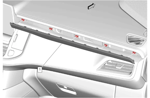
- Using a flat-bladed plastic trim tool, release the retaining clips.
- Instrument Panel Trim Plate Applique (1) » Remove
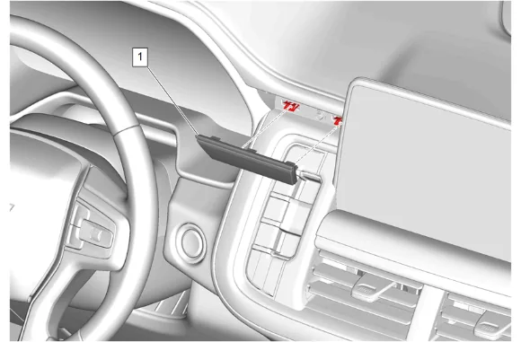
- Using a flat-bladed plastic trim tool, release the retaining clips.
- Instrument Panel Center Trim Plate Applique (1) » Remove
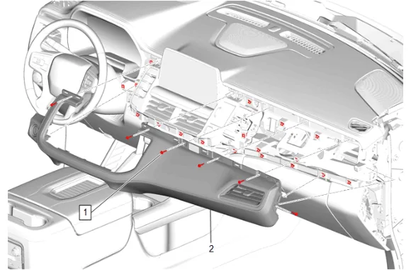
- Instrument Panel Upper Trim Panel Bolt (1) » Remove [6x]
- Using a flat-bladed plastic trim tool, release the retaining clips.
- Disconnect the electrical connector.
- Instrument Panel Trim Pad (2) » Remove
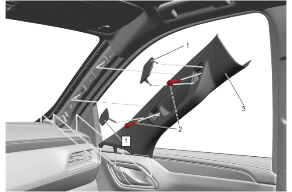
- Reposition the weatherstrip as necessary.
- Windshield Pillar Assist Handle Cover (1) » Remove [2x]
- Windshield Pillar Assist Handle Bolt (2) » Remove [2x]
- Windshield Garnish Molding (3) » Remove
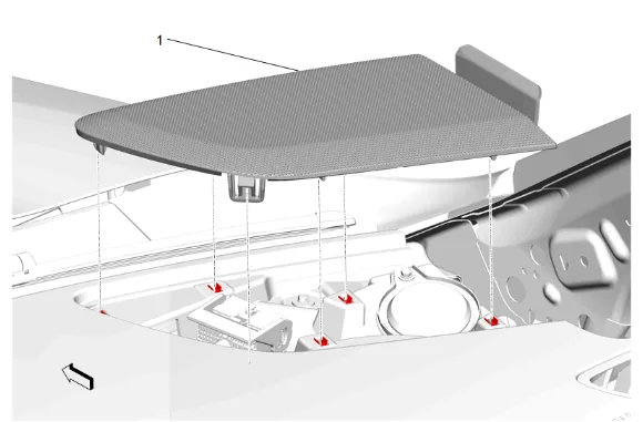
- Using a flat-bladed plastic trim tool, release the retaining clips.
- Radio Front Speaker Grille (1) » Remove
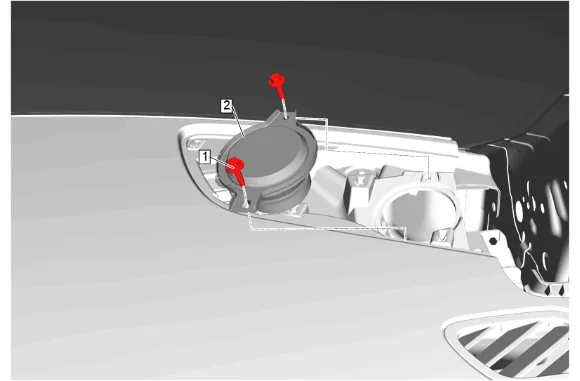
- Radio Front Speaker Bolt (1) » Remove [2x]
- Radio Front Speaker (2) » Remove
- Disconnect the electrical connector.
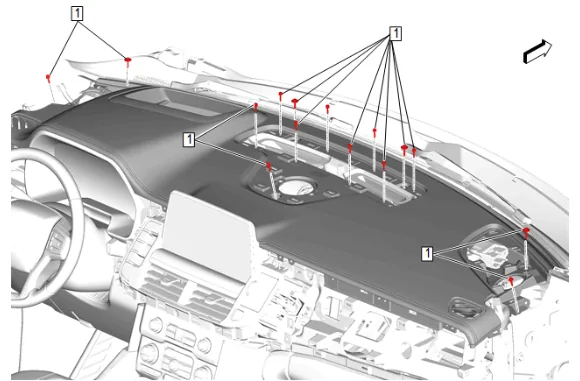
- Instrument Panel Upper Trim Panel Bolt (1) » Remove [15x]
- Disconnect the electrical connector.
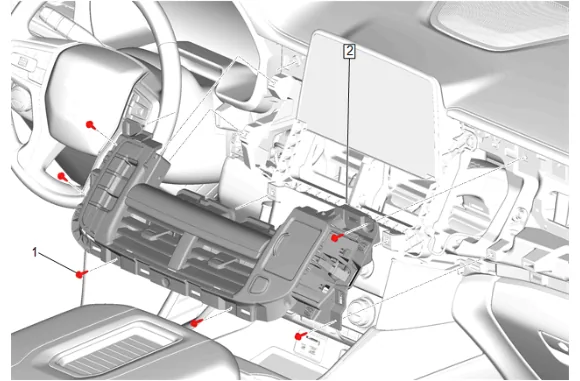
- Instrument Panel Center Trim Panel Bolt (1) » Remove [6x]
- Disconnect the electrical connectors.
- Instrument Panel Transmission Shift Opening Cover (2) » Remove
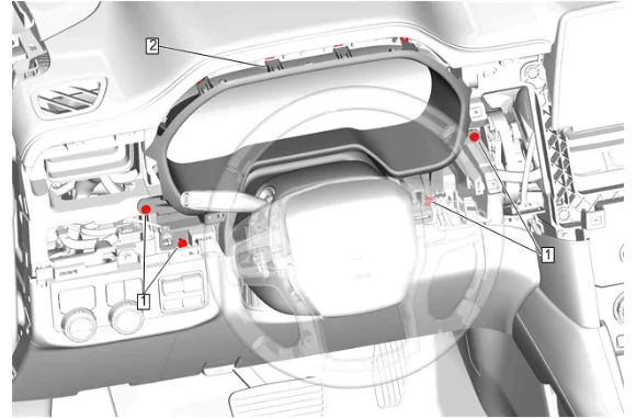
- Instrument Panel Cluster Trim Plate Bolt (1) » Loosen [4x]
- Using a flat-bladed plastic trim tool, release the retaining clips.
- Instrument Panel Cluster Trim Plate (2) » Loosen
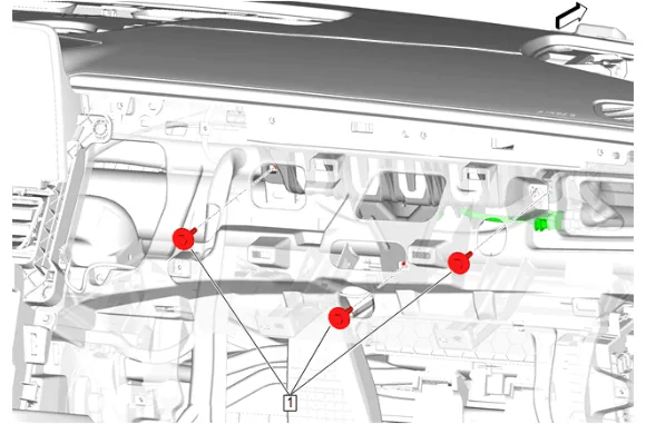
- Instrument Panel Airbag Bolt (1) » Remove [3x]
- Disconnect the electrical connector.
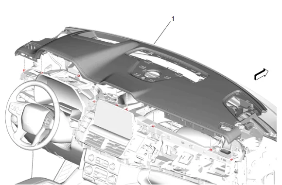
- Remove the instrument panel upper trim panel (1) with the aid of an assistant.
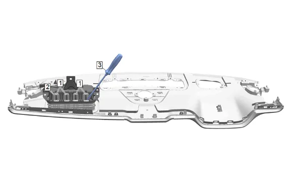
- Insert the flat tip driver (3) in between the airbag chute (2) and the air bag module hook (1) at the dotted line or base of hook , as shown above in graphic.
- Tilt the flat tip driver forward until the air bag module hooks (1) break or bend enough to relieve the tension and allow for easier removal of the airbag from the chute.
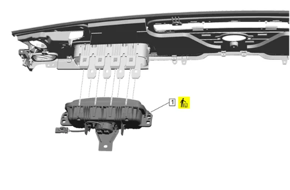
- Instrument Panel Airbag (1) » Remove and DISCARD
- Inflatable Restraint Module Handling and Scrapping Installation Procedure
- Position the instrument panel airbag (1) on the air bag chute.
-
Push the instrument panel airbag (1) into the airbag chute until the hooks of airbag module are seated completely.
-
Install the instrument panel upper trim panel (1) with the aid of an assistant.
-
Connect the electrical connector.
-
Instrument Panel Airbag Bolt (1) » Install and tighten [3x] — Fastener Specifications
-
Instrument Panel Cluster Trim Plate (2) » Install
-
Instrument Panel Cluster Trim Plate Bolt (1) » Tighten [4x] — Fastener Specifications
-
Connect the electrical connectors.
-
Instrument Panel Transmission Shift Opening Cover (2) » Install
-
Instrument Panel Center Trim Panel Bolt (1) » Install and tighten [6x] — Fastener Specifications
-
Instrument Panel Upper Trim Panel Bolt (1) » Install and tighten [15x] — Fastener Specifications
-
Connect the electrical connector.
-
Radio Front Speaker (2) » Install
-
Radio Front Speaker Bolt (1) » Install and tighten [2x] — Fastener Specifications
-
Radio Front Speaker Grille (1) » Install
-
Windshield Garnish Molding (3) » Install
-
Windshield Pillar Assist Handle Bolt (2) » Install and tighten [2x] — Fastener Specifications
-
Windshield Pillar Assist Handle Cover (1) » Install [2x]
-
Reposition the weatherstrip as necessary.
-
Connect the electrical connector.
-
Instrument Panel Trim Pad (2) » Install
-
Instrument Panel Upper Trim Panel Bolt (1) » Install and tighten [6x] — Fastener Specifications
-
Instrument Panel Center Trim Plate Applique (1) » Install
-
Instrument Panel Trim Plate Applique (1) » Install
-
Instrument Panel Fuse Block Access Hole Cover (1) » Install
-
Connect the electrical connector.
-
Radio Front Center Speaker (2) » Install
-
Radio Front Center Speaker Bolt (1) » Install and tighten [2x] — Fastener Specifications
-
Connect the electrical connector.
-
Instrument Panel Extension (1) » Install
-
Connect the electrical connector.
-
Radio Front Speaker (2) » Install
-
Radio Front Speaker Bolt (1) » Install and tighten [2x] — Fastener Specifications
-
Radio Front Speaker Grille (1) » Install
-
Windshield Garnish Molding Bolt (2) » Install and tighten — Fastener Specifications
-
Align the retaining clips with the slots in the A pillar and press the windshield garnish molding (1) into place.
-
Windshield Garnish Molding (1) » Install
-
Reposition the weatherstrip as necessary.
-
Connect the electrical connectors.
-
Instrument Panel Switch Trim Plate (2) » Install
-
Instrument Panel Switch Trim Plate Bolt (1) » Install and tighten — Fastener Specifications
-
Connect the electrical connectors.
-
Instrument Panel Trim Pad (2) » Install
-
Instrument Panel Trim Pad Bolt (1) » Install and tighten [2x] — Fastener Specifications
-
Instrument Panel Trim Plate Applique (1) » Install
-
Instrument Panel Fuse Block Access Hole Cover (1) » Install
-
Instrument Panel Lower Trim Panel Outer Filler (1) » Install
-
Enable the SIR System. SIR Disabling and Enabling