Steering Linkage Inspection
Special Tools GE-8001 Magnetic Base Dial Indicator Equivalent regional tools: Special Tools Steering Linkage Outer Tie Rod
- Raise and support the vehicle. Lifting and Jacking the Vehicle
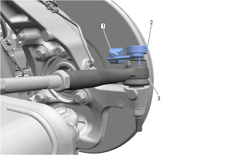
- Install a magnetic base (1) to the front brake shield at the location shown above.
- Install GE-8001 Magnetic Base Dial Indicator (2) to the steering linkage outer tie rod (3) with the contact point at the location shown above.
- Ensure GE-8001 Magnetic Base Dial Indicator (2) is set at zero before taking a measurement.
- Using a flat bladed tool, induce an upward and downward motion on the steering linkage outer tie rod (3).
- If movement exceeds 1.0 mm (0.039 in) replace the steering linkage outer tie rod. Steering Linkage Outer Tie Rod Replacement Steering Linkage Inner Tie Rod
- Raise and support the vehicle. Lifting and Jacking the Vehicle
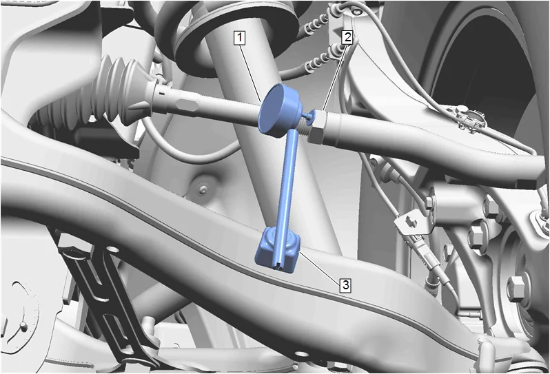
- Install a magnetic base (3) to the lower control arm at the location shown above.
- Install GE-8001 Magnetic Base Dial Indicator (1) to the steering linkage inner tie rod nut (2) with the contact point at the location shown above.
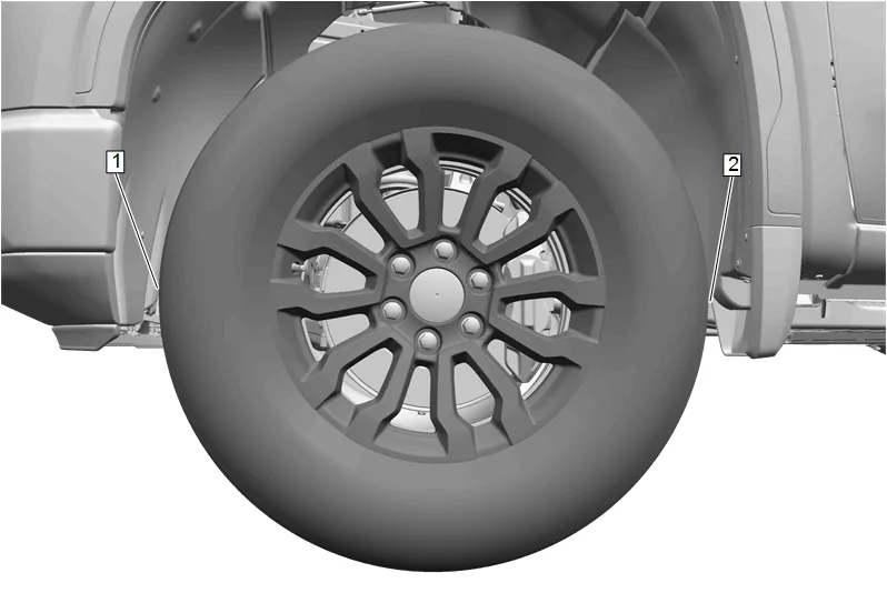
- Grasping the tire at the 3 o’clock (2) and 9 o’clock (1) positions, gently push in on one side of the tire in order to remove any lash.
- Ensure GE-8001 Magnetic Base Dial Indicator is set at zero before taking a measurement.
- On the same side of the tire previously pushed in, gently pull out and measure the lash.
- If the movement exceeds 0.5 mm (0.02 in), replace the steering linkage inner tie rod. Steering Linkage Inner Tie Rod Replacement