Differential Pinion Input Shaft Runout Measurement
Vibration Diagnosis and Correction | Diagnostic Information and Procedures | Document ID: 5044705 Special Tools GE-7872 Magnetic Base Dial Indicator Set, or equivalent For equivalent regional tools. Special Tools and Equipment
- Place the transmission in NEUTRAL.
- Raise and support the vehicle. Lifting and Jacking the Vehicle
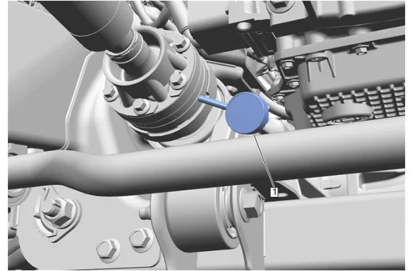
- If equipped with a CV joint, measure the drive axle pinion input shaft radial runout on the CV join outer race of the propeller shaft CV joint housing, as close to the flange as possible: 3.1. Clean the surface of the propeller shaft rear CV joint housing just ahead of the drive axle input flange. 3.2. Mount a dial indicator set (1), GE-7872 Magnetic Base Dial Indicator Set and position the dial indicator to contact the propeller shaft CV joint housing as close to the drive axle input flange as possible.
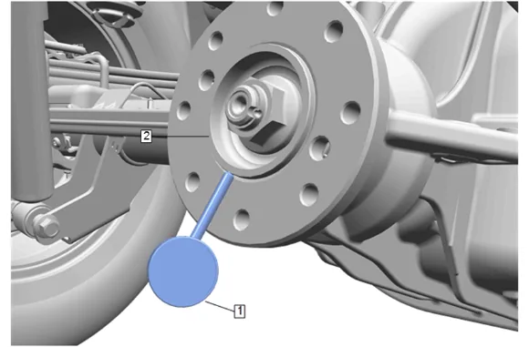
- If equipped with a rubber coupling or bolt-on universal joint yoke, measure the differential pinion input shaft radial runout on the machined surface of the flange pilot area: 4.1. Mark the position of the propeller shaft to the drive axle input flange. 4.2. Separate the propeller shaft from the drive axle input flange. 4.3. Clean the surface of the flange pilot area (2). 4.4. Mount a dial indicator set (1), GE-7872 Magnetic Base Dial Indicator Set and position the dial indicator to contact the round diameter of the flange pilot area (2).
- If equipped with a strap style universal joint flange, measure the differential pinion input shaft radial runout at the propeller shaft, as close to the flange as possible: 5.1. Clean the surface of the propeller shaft just ahead of the input flange. 5.2. Mount a dial indicator set, GE-7872 Magnetic Base Dial Indicator Set and position the dial indicator to contact a smooth area of the propeller shaft as close to the end of the shaft as possible.
- Rotate the drive axle input shaft by hand to locate the low spot.
- Set the dial indicator to zero on the low spot.
- Rotate the shaft by hand and record the amount of radial runout.
- If equipped with a constant velocity (CV) joint, rubber coupling, or bolt on universal joint yoke: 9.1. Compare the runout of the shaft to the runout tolerance specifications guidelines. 9.2. If the drive axle input shaft runout exceeds the specification, the flange requires replacement.