Power Steering Wiring Harness Extension Harness Replacement (Without RC1)
Power Steering Wiring Harness Extension Harness Replacement (Without RC1)
- Disconnect the battery negative cable. Battery Negative Cable Disconnection and Connection
- Raise and support the vehicle. Lifting and Jacking the Vehicle
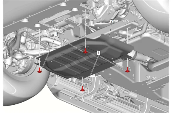
- Underbody Skid Shield Bolt (1) » Remove [4x]
- Underbody Skid Shield (2) » Remove
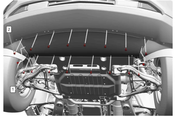
- Front Bumper Fascia Air Deflector Bolt (1) » Remove [10x]
- Front Bumper Fascia Extension Bolt (2) » Remove [8x]
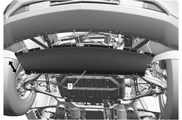
- Pull the front bumper fascia extension (1) rearward and down from the front bumper fascia.
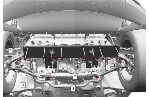
- Front Bumper Fascia Extension Bolt (2) » Remove [4x]
- Pull the front bumper fascia extension (4) rearward and down.
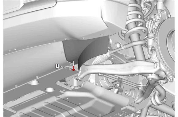
- { If equipped } Front Tire Front Air Deflector Bolt (1) » Remove
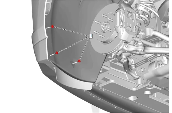
- Front Wheelhouse Liner Bolt (1) » Remove [3x]
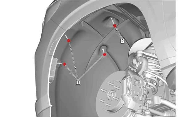
- Front Wheelhouse Liner Bolt (1) » Remove [3x]
- Front Wheelhouse Liner Retainer (2) » Remove
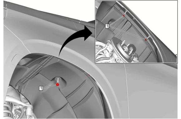
- Front Wheelhouse Liner Bolt (1) » Remove [3x]
- Reposition the front wheelhouse liner rearward.
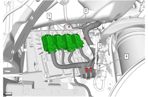
- Disconnect the electrical connectors. (1)
- Engine Wiring Harness Retainer (2) » Disengage [2x]
- Engine Wiring Harness Channel Retainer (3) » Remove [2x]
- Engine Wiring Harness (4) » Reposition
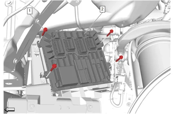
- Engine Control Module Bolt (1) » Remove [4x]
- Engine Control Module (2) » Remove
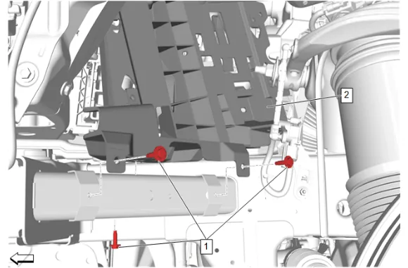
- Engine Control Module Bracket Bolt (1) » Remove [3x]
- Engine Control Module Bracket (2) » Reposition
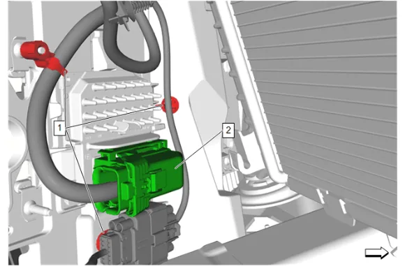
- Engine Wiring Harness Retainer (1) » Disengage [2x]
- Disconnect the electrical connector. (2)
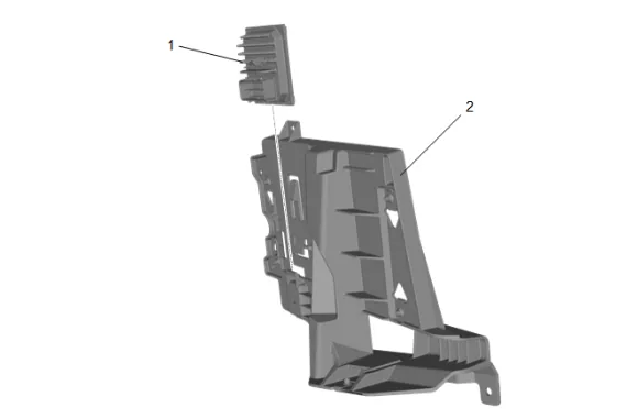
- Use a suitable tool to release the locking tab and remove the transmission control module (1) by sliding it out from the engine control module bracket (2).
- Engine Control Module Bracket (2) » Remove
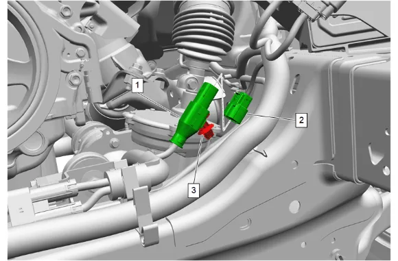
- Remove the power steering assist motor wire clip (3).
- Disconnect the power steering harness extension harness (1) from the main chassis harness (2).
-
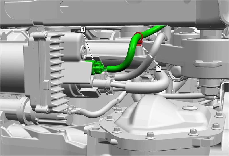
Disconnect the power steering harness extension harness (1) from the power steering assist motor.
-
Remove the power steering harness extension harness clip (2) from the electric belt drive rack and pinion steering gear housing.
-
Remove the power steering harness extension harness. Installation Procedure
-
Install the power steering harness extension harness.
-
Install the power steering harness extension harness clip (2) to the electric belt drive rack and pinion steering gear housing.
-
Connect the power steering harness extension harness (1) to the power steering assist motor.
-
Connect the power steering harness extension harness (1) to the main chassis harness (2).
-
Install the power steering assist motor wire clip (3).
-
Engine Control Module Bracket (2) » Move into position
-
Connect the electrical connector. (2)
-
Engine Wiring Harness Retainer (1) » Engage [2x]
-
Engine Control Module Bracket (2) » Install
-
Engine Control Module Bracket Bolt (1) » Install and tighten [3x] — Fastener Specifications
-
Engine Control Module (2) » Install
-
Engine Control Module Bolt (1) » Install and tighten [4x] — Fastener Specifications
-
Engine Wiring Harness Retainer (1) @ Engine Control Module Bolt » Engage
-
Engine Wiring Harness (4) » Install
-
Engine Wiring Harness Channel Retainer (3) » Install [2x]
-
Engine Wiring Harness Retainer (2) » Engage [2x]
-
Connect the electrical connectors. (1)
-
Reposition the front wheelhouse liner forward.
-
Front Wheelhouse Liner Bolt (1) » Install and tighten [3x] — Fastener Specifications
-
Front Wheelhouse Liner Retainer (2) » Install
- Front Wheelhouse Liner Bolt (1) » Install and tighten [3x] — Fastener Specifications
-
Front Wheelhouse Liner Bolt (1) » Install and tighten [3x] — Fastener Specifications
-
{ If equipped } Front Tire Front Air Deflector Bolt (1) » Install and tighten — Fastener Specifications
-
Front Bumper Fascia Extension (4) » Install
-
Front Bumper Fascia Extension Bolt (2) » Install and tighten [4x] — Fastener Specifications
-
Front Bumper Fascia Extension (1) » Install
-
Front Bumper Fascia Extension Bolt (2) » Install and tighten [8x] — Fastener Specifications
-
Front Bumper Fascia Air Deflector Bolt (1) » Install and tighten [10x] — Fastener Specifications
-
Underbody Skid Shield (2) » Install
-
Underbody Skid Shield Bolt (1) » Install and tighten [4x] — Fastener Specifications
-
Remove the supports and lower the vehicle.
-
Connect the battery negative cable. Battery Negative Cable Disconnection and Connection
-
Clear DTCs.