Wiring Systems and Power Management | Schematic and Routing Diagrams | Document ID: 3293350
Information Overview
The following explains some of the key parts of the GM wiring diagrams. Included are:
Color Abbreviations
Electronic Delivery Navigation Features
Color Abbreviations
The following sequence is used when depicting wire colors:
Color modifier of the wire, such as light or dark (if applicable)
Primary color of the wire
Secondary color of the wire (tracer/stripe)
Wire insulation and connector body colors in schematic information are abbreviated with a two character
code as listed below.
Abbreviation
Color
Abbreviation
Color
AM
Amber
OG
Orange
BARE
Bare
PK
Pink
BG
Beige
PU
Purple
BK
Black
RD
Red
BN
Brown
RU
Rust
BU
Blue
SR
Silver
CL
Clear
TL
Teal
CR
Cream
TN
Tan
CU
Curry
TQ
Turquoise
GD
Gold
VT
Violet
GN
Green
WH
White
GY
Gray
YE
Yellow
NA
Natural
—
—
Color Modifiers
L
Light
D
Dark
Additionally, industry standard cable types are not identified by color, but are listed by cable type as follows:
Abbreviation
Cable Type
COAX
Coax Cable
Abbreviation
Cable Type
FW
Flat Wire
HDMI
High Definition Multimedia Interface
LDVS
Low-voltage Differential Signaling
TWINAX
Twinax Cable
USB
Universal Serial Bus
Electronic Delivery Navigation Features
The schematics information has been enhanced for electronic delivery and the following explains the features
that are now available.
The enhanced features are categorized into three types:
Mouse-overs, which are active when the mouse pointer is placed over the activated area
Hotspots (links to other information), which are active by placing the mouse pointer over the activated
area and clicking the left mouse button
Hotspot Target Highlighting, which is when linking from one graphic to another graphic, the point of
interest will be highlighted in red. This feature is available only when linking from a schematic graphic
to a component locator/harness routing view, or when linking from a schematic to an electrical center
identification view
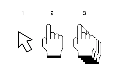
Depending on the amount of information that is linked to from a hotspot, the mouse pointer changes shape.
How to Use Electrical Schematics — figure 1
Basic mouse pointer – this means there are no hotspots available, but there may be a mouse-over
available.
Single hand pointer – this means there is a mouse-over and hotspot link to a single document. Clicking
on these areas will automatically take you to the target link.
Multiple hand pointer – this means there is a mouse-over and hotspot link to a multiple document.
Clicking on these areas will bring up a pop-up menu that will display all available links. You may then
select one of the available links clicking on one of the displayed links.
To see which areas of the schematic information have an available hotspot and/or a mouse-over, select and
hold down the highlight hotspots button of the cgm viewer. This will highlight all areas of the graphic that
have an available hotspot and/or a mouse-over in red. Once the button is released, the areas of the graphic
will no longer be highlighted.
Each type of schematic related information has some level of these features. The schematic related information
consists of the following information types:
Schematics
Connector End Views
Component Locator Views
Harness Routing Views
Electrical Center Identification Views
Master Electrical Component List
Master Electrical Schematic Icons
Schematics RPO Code List
Circuit Number/Wire Colors
Wire Lines
Connector Cavities
Schematics
An electrical schematic hotspot is an activated icon or area in the schematic that can be cursor selected to
link to additional information. Additionally, each of the hotspots in schematics has a mouse-over.
Hotspots in schematics are categorized into three types:
Schematic Navigational Icon Hotspots
Schematic Informational Icon Hotspots
Schematic Navigational Hotspots
Schematic Navigational Icon Hotspots
The following lists icons that may appear on the upper right corner of a schematic that have an available
mouse-over and hotspot.
Icon
Mouse-Over
Hotspot Link to Information
Master Electrical Component List
Links to the vehicle Master Electrical Component List that shows all electrical components and harness items on the vehicle and has links to any available views
Title of the subsystem description and operation
Links to the System Description and Operation
Control Module References
Links to the Control Module References table
Title of the next schematic page
Links to the next schematic of the subsystem schematics
How to Use Electrical Schematics — figure 2How to Use Electrical Schematics — figure 3How to Use Electrical Schematics — figure 4How to Use Electrical Schematics — figure 5
Icon
Mouse-Over
Hotspot Link to Information
Title of the previous schematic page
Links to the previous schematic of the subsystem schematics
How to Use Electrical Schematics — figure 6
Schematic Informational Icon Hotspots
The following lists the icons that may appear anywhere on a schematic that have an available mouse-over
and hotspot.
Icon
Mouse-Over
Hotspot Link to Information
Danger
Master Electrical Schematic Icons
Links to the vehicle Master Electrical Schematic Icons list that describes the message for the icon.
High Voltage
Master Electrical Schematic Icons
Links to the vehicle Master Electrical Schematic Icons list that describes the message for the icon.
Caution
Master Electrical Schematic Icons
Links to the vehicle Master Electrical Schematic Icons list that describes the message for the icon.
How to Use Electrical Schematics — figure 7How to Use Electrical Schematics — figure 8
Icon
Mouse-Over
Hotspot Link to Information
Supplemental Restraint
Master Electrical Schematic Icons
Links to the vehicle Master Electrical Schematic Icons list that describes the message for the icon.
Pedestrian Impact
Master Electrical Schematic Icons
Links to the vehicle Master Electrical Schematic Icons list that describes the message for the icon.
Additional Information
Master Electrical Schematic Icons
Links to the vehicle Master Electrical Schematic Icons list that describes the message for the icon.
How to Use Electrical Schematics — figure 9How to Use Electrical Schematics — figure 10How to Use Electrical Schematics — figure 11How to Use Electrical Schematics — figure 12
Schematic Navigational Hotspots
In addition to the navigational icons, schematics have other active hotspots that link to supporting
information such as related schematics, component locator views, harness routing views, and connector end
views.
These hotspots can be either text based or symbol based. The following are the items that will have a
mouse-over and hotspot.
Schematic Title Circuit References
How to Use Electrical Schematics — figure 13
Mouse-over: Displays the title of the schematic page linked to.
Hotspot Link to Information: Links to the individual subsystem schematic page(s) that shows the
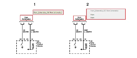
circuit in detail. If multiple circuits are included, or if the circuit is shown in multiple schematics, a menu
will appear when the link is selected. This menu includes links to all schematics that contain the same
circuit number as the circuit being referenced. Additionally, when the target schematic is opened, the
referenced circuit will be highlighted to draw visual attention. Note that when there are multiple target
links, the links may appear to be duplicate in the menu, however, they are not. The exact same title is
repeated for each circuit number that is pointing to the same target schematic. A future update will
include the circuit number before the link description to further assist in link selection.
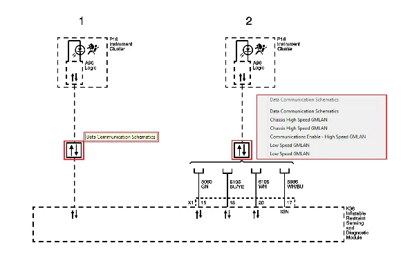
Serial Data Functional Circuit Icon
How to Use Electrical Schematics — figure 14
Mouse-over: Displays the schematic title Data Communication Schematics.
Hotspot Link to Information:
⇒ When a dashed serial data wire and icon are shown without any circuit numbers, the serial data circuit
icon will link to the complete list of Data Communication schematic pages, and not a specific
schematic. This is due to no circuit numbers are shown.
⇒ When a circuit wire(s) are shown with circuit numbers, a menu will appear when the link is selected.
This menu includes links to the list of Data Communication schematic pages as well as links to the
individual schematics that contain the same circuit number as the circuit being referenced.
Additionally, when the target schematic is opened, the referenced circuit will be highlighted to draw
visual attention. Note that when there are multiple target links, the links may appear to be duplicate
in the menu, however, they are not. The exact same title is repeated for each circuit number that is
pointing to the same target schematic. A future update will include the circuit number before the link
description to further assist in link selection.
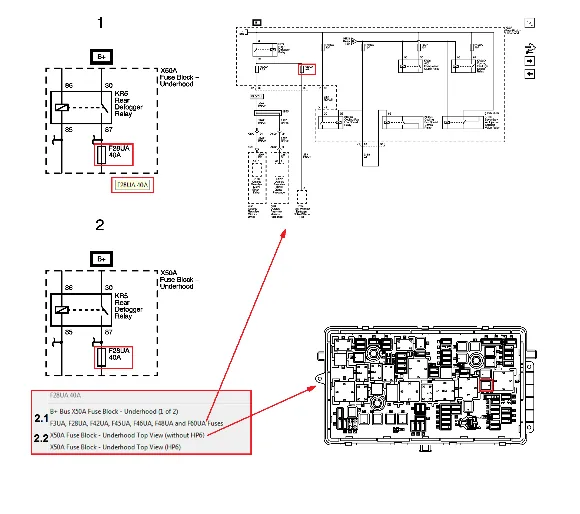
Fuse/Circuit Breaker Symbol and Name within Subsystem Schematics
How to Use Electrical Schematics — figure 15
Mouse-over: Displays the code and the amperage of the protection device.
Hotspot Link to Information:
⇒ When multiple links are available, a menu will appear when the link is selected. This menu includes all
available links in a structured sequence.
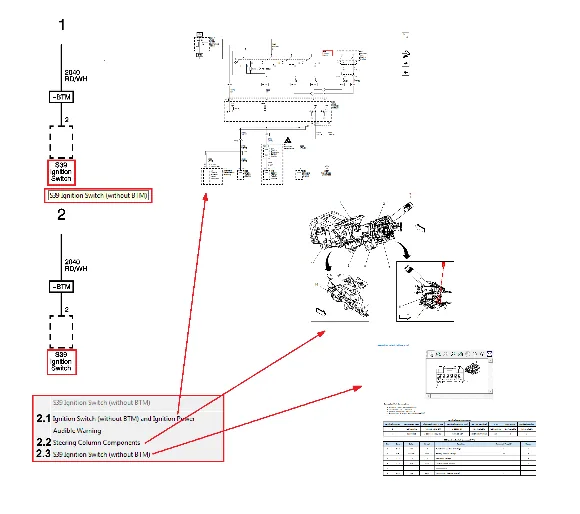
2.1. Links to the individual schematic page(s) within the Power Distribution Schematics where the
circuits are shown in detail. Additionally, when the target schematic is opened, the circuit protection
device will be highlighted to draw visual attention.
2.2. Links to individual fuse block top or bottom view(s) within the Electrical Center Identification Views
and will show where the device is located in the fuse block. Additionally, when the target view is
opened, the device outline will be highlighted for visual attention.
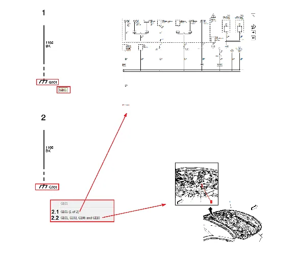
Ground Symbol/Name in Subsystem Schematics
How to Use Electrical Schematics — figure 16
Mouse-over: Displays the ground number.
Hotspot Link to Information:
⇒ When multiple links are available, a menu will appear when the link is selected. This menu includes all
available links in a structured sequence.
2.1. Links to the individual schematic page(s) within the Ground Distribution Schematics where the
circuits are shown in detail. Additionally, when the target schematic is opened, the ground will be
highlighted to draw visual attention.
2.2. Links to the individual locator view(s) within the Ground Views and will show where the ground is
located on the vehicle. Additionally, when the target view is opened, the ground and callout leader
line/number will be highlighted to draw visual attention.
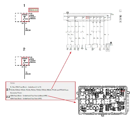
Body Control Module High-Side Driver Output Symbol/Driver Source Fuse Name in Subsystem
Schematics
How to Use Electrical Schematics — figure 17
Mouse-over: Displays the code of the protection device that supplies the high-side driver output circuit.
Hotspot Link to Information:
⇒ When multiple links are available, a menu will appear when the link is selected. This menu includes all
available links in a structured sequence.
2.1. Links to the individual schematic page(s) within the Power Distribution Schematics where the
circuits are shown in detail. Additionally, when the target schematic is opened, the circuit protection
device will be highlighted to draw visual attention.
2.2. Links to individual fuse block top or bottom view(s) within the Electrical Center Identification Views
and will show where the device is located in the fuse block. Additionally, when the target view is
opened, the device outline will be highlighted for visual attention.
Component Name in Power and Ground Distribution Schematics
How to Use Electrical Schematics — figure 18
Mouse-over: Displays the code and name of the component.
Hotspot Link to Information:
⇒ When multiple links are available, a menu will appear when the link is selected. This menu includes all
available links in a structured sequence.
2.1. Links to the individual schematic page(s) within the Subsystem Schematic(s) where the circuits are
shown in detail. Additionally, when the target schematic is opened, the component code and name
will be highlighted to draw visual attention.
2.2. Links to the individual locator view(s) within the applicable component view category and will show
where the component is located on the vehicle. Additionally, when the target view is opened, the
component and callout leader line/number will be highlighted to draw visual attention.
2.3. Links to individual connector end view(s) within the Component Connector End Views.
Twisted Pair Symbols
How to Use Electrical Schematics — figure 19
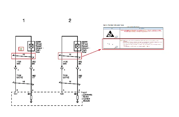
Mouse-over: Displays the repair specification for the number of twists of the wire within the specified
distance.
Hotspot Link to Information: Links to the Master Electrical Schematic Icons list that shows the icon
along with the repair specification details for the wire.
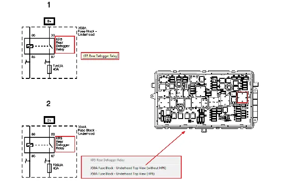
Relay Name (located within a block)
How to Use Electrical Schematics — figure 20
Mouse-over: Displays the relay code and name.
Hotspot Link to Information: Links to individual fuse block top or bottom view(s) within the Electrical
Center Identification Views and will show where the device is located in the fuse block. Additionally, when
the target view is opened, the device outline will be highlighted for visual attention.
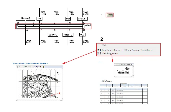
Component Name in Subsystem Schematics
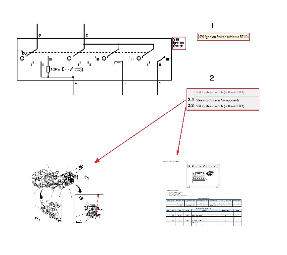
How to Use Electrical Schematics — figure 21
Mouse-over: Displays the code and name of the component.
Hotspot Link to Information:
⇒ When multiple links are available, a menu will appear when the link is selected. This menu includes all
available links in a structured sequence.
2.1. Links to the individual locator view(s) within the applicable component view category and will show
where the component is located on the vehicle. Additionally, when the target view is opened, the
component and callout leader line/number will be highlighted to draw visual attention.
2.2. Links to individual connector end view(s) within the Component Connector End Views.
Splice Names
Mouse-over: Displays the code of the harness splice.
Hotspot Link to Information: Links to the individual harness routing view(s) within the Harness
Routing Views and will show where the harness item is located on the vehicle harness. Additionally, when
the target view is opened, the harness item and callout leader line/number will be highlighted to draw
visual attention.
Splice Pack Names
How to Use Electrical Schematics — figure 22
Mouse-over: Displays the code of the harness splice pack.
Hotspot Link to Information:
⇒ When multiple links are available, a menu will appear when the link is selected. This menu includes all
available links in a structured sequence.
2.1. Links to the individual harness routing view(s) within the Harness Routing Views and will show
where the harness item is located on the vehicle harness. Additionally, when the target view is
opened, the harness item and callout leader line/number will be highlighted to draw visual
attention.
2.2. Links to individual connector end view(s) within the Splice Pack Connector End Views.
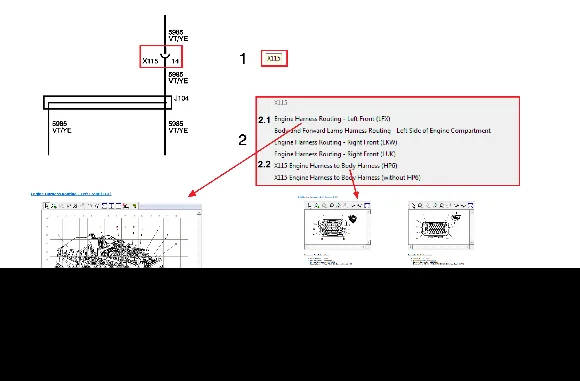
Inline Harness Connector Names
How to Use Electrical Schematics — figure 23
Mouse-over: Displays the code of the inline harness connector.
Hotspot Link to Information:
⇒ When multiple links are available, a menu will appear when the link is selected. This menu includes all
available links in a structured sequence.
2.1. Links to the individual harness routing view(s) within the Harness Routing Views and will show
where the harness item is located on the vehicle harness. Additionally, when the target view is
opened, the harness item and callout leader line/number will be highlighted to draw visual
attention.
2.2. Links to individual connector end view(s) within the Inline Harness Connector End Views.
Regular Production Option (RPO) Codes/Icons
Mouse-over: Displays the description of the RPO code as well as the country group names where the
option is possible to order. Note that each RPO shown will have its own mouse-over and description. Also
note that the mouse-over does not include any symbols indicating with (shown as a + sign if combined
option) or without (shown as a – sign to mean without/except).
Hotspot Link to Information: Links to the Schematics RPO Code List that shows the RPO, the
description of the option, and the country group names where the option is possible to order.
Circuit Number/Wire Colors
Mouse-over: Displays the circuit number (if shown) and the color abbreviation of the wire insulation.
Refer to Color Abbreviations for an explanation of each wire color abbreviation. A future update may spell
out the wire colors in all languages.
Hotspot Link to Information: None at this time.
Wire Lines
Mouse-over: Displays the circuit function of the wire as used on the vehicle. This same function is
shown in the connector end view pinout table for the component the wire connects. Note if there is no
circuit number shown, the circuit will not have an associated mouse-over.
Hotspot Link to Information: None at this time. A future update may include links to harness routing
views to show the routing of the circuit within the vehicle harness.
Connector Identifiers and Cavities
Mouse-over: Displays the cavity (pin) identifier (letter/number) for the connection at the component or
inline harness connection.
Hotspot Link to Information: None at this time.
Connector End Views
Connector end view graphics now have mouse-overs to show the wire details of each of the populated
cavities. Additionally, the terminal part information has been restructured into an easier to read table.
Mouse-over: Displays all of the pinout table information for each column including Pin, Size, Color,
Circuit, Function, Terminal Type ID, and Option. Note, that not used/not occupied cavities will not have a
mouse-over at all. For not used/not occupied cavities, the connector graphic will appear to have a
mouse-over, but no information will be displayed in a pop-up menu.
Hotspot Link to Information: None at this time. A future update may include links to individual
subsystem schematic(s) for each circuit.
Component Locator Views
Component locator views now have links to component connector end views.
Mouse-over: Displays the code and name of the component.
Hotspot Link to Information: Links to individual connector end view(s) within Component Connector
End Views.
Harness Routing Views
Harness routing views now have links to splice pack and inline harness connector end views.
Mouse-over: Displays the code of the harness item.
Hotspot Link to Information: Links to individual splice pack connector end view(s) within Splice Pack
Connector End Views for splice packs and to the individual inline harness connector end view(s) within
Inline Harness Connector End Views for inline harness connectors.
Electrical Center Identification Views
Electrical center identification views (top and bottom/front and back) graphics now have mouse-overs to
show the function details of each of utilized devices. Note that the label view will not have any mouse-overs
or links at all.
Mouse-over: Displays all of the usage table information for each column including No., Device Label
Name, Device Assigned Name, Rating, and Description. Note, that not used/not occupied devices will not
have a mouse-over at all. For not used/not occupied devices, the device graphic may appear to have a
mouse-over, but no information will be displayed in a pop-up screen.
Hotspot Link to Information: None at this time.
Master Electrical Component List
While the master electrical component list format has not changed, it will continue to have links to
component locator, harness routing, and connector end views for each of the available electrical devices
within the vehicle.
Mouse-over: None at this time.
Hotspot Link to Information:
⇒ A future update may include links to individual subsystem schematic(s) for each component/harness
item.
⇒ Components
– Links to individual locator view within one of the eight component view categories and will show where
the component is located in the vehicle.
– Links to individual connector end view(s) within Component Connector End Views.
⇒ Electrical Centers (Fuse Blocks)
– Links to individual locator view within one of the eight component view categories and will show where
the component is located in the vehicle.
– Links to individual connector end view(s) within Electrical Center Identification Views.
⇒ Inline Harness Connectors
– Links to individual harness routing view(s) within Harness Routing Views and will show where the
harness item is located on the vehicle harness.
– Links to individual connector end view(s) within Inline Harness Connector End Views.
⇒ Grounds
– Links to individual locator view within Ground Views component view and will show where the ground
⇒ Splices
– Links to individual harness routing view(s) within Harness Routing Views and will show where the
harness item is located on the vehicle harness.
⇒ Splice Packs
– Links to individual harness routing view(s) within Harness Routing Views and will show where the
harness item is located on the vehicle harness.
– Links to individual connector end view(s) within Splice Pack Connector End Views.
Master Electrical Schematic Icons
While the master electrical schematic icons list format has not changed, it will continue to include icons used
in the vehicle schematics along with the message for the icon.
Mouse-over: None at this time.
Hotspot Link to Information: None at this time.
Schematic RPO Code List
The schematic RPO code list only includes RPOs shown in schematics and also includes the country groupings
for the options. This list is in addition to the vehicle RPO Code List that is included in General Information.