Driveline Working Angles Measurement
Vibration Diagnosis and Correction | Diagnostic Information and Procedures | Document ID: 5044714 Special Tools J-23498-A Driveshaft Inclinometer, or equivalent J-23498-20 Driveshaft Inclinometer Adapter, or equivalent For equivalent regional tools. Special Tools and Equipment
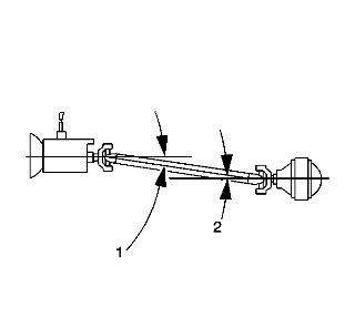
The working angle of a universal joint is formed by the difference between the angles of any 2 shafts that intersect. Propeller shaft systems that have 1 universal joint have 1 working angle; systems with 2 universal joints have 2 working angles, and so on. In a typical 1-piece propeller system with 2 universal joints, the working angles are front (1) and rear (2): The front working angle (1) is formed by the intersection of the transmission or transfer case output shaft and the propeller shaft. The rear working angle (2) is formed by the intersection of the propeller shaft and the drive axle pinion.
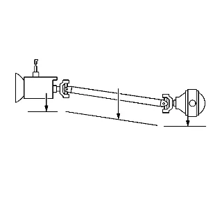
Be sure to accurately record the measurements taken on a diagram, similar to the one shown. Measurement Procedure
- For vehicles with solid axles, ensure that the vehicle has a full tank of fuel or the equivalent amount of weight in the correct location to simulate a full tank. The weight of 3.8 L (1 gal) of gasoline is approximately 2.8 kg (6.2 lb).
- Raise and support the vehicle. On vehicles with solid axles, ensure that the drive axle is supported at ride height—vehicle body supported by suspension components. Suspension travel will not affect driveline angles on vehicles with direct-mounted drive axles. Ensure the wheels are free to rotate. Refer to Lifting and Jacking the Vehicle.
- For vehicles with 2-piece propeller shaft systems, inspect the lateral alignment of the propeller shafts before proceeding: 3.1. From underneath the propeller shafts, look down the length of the shafts from front to rear. Inspect the alignment of the shafts to each other. 3.2. From underneath the shafts, if the propeller shafts are not aligned to each other in a straight line, then the lateral alignment of the propeller shafts needs to be adjusted before proceeding. The propeller shaft support bearing assembly can be relocated slightly to one side in order to improve the alignment of the shafts. Ensure that you do not create a ground-out condition against the exhaust or any other component.
- Place the transmission in NEUTRAL.
- Clean any corrosion or foreign material from the universal joint bearing caps.
- Remove any of the universal joint bearing cap snap rings that may interfere with the correct placement of the J-23498-A Driveshaft Inclinometer, or equivalent .
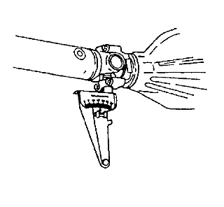
- For all propeller systems perform the first measurement: 7.1. Rotate the propeller shaft to align the rear-most yoke flanges vertically. 7.2. Install the J-23498-A Driveshaft Inclinometer, or equivalent to the lower universal joint bearing cap of the rear-most yoke. This yoke may be part of a propeller shaft, torque tube input shaft, or a drive axle pinion shaft. Measure and record the angle of the shaft.
- For propeller systems with 2 or 3 universal joints, perform this additional measurement: Without rotating the propeller, install the J-23498-A Driveshaft Inclinometer, or equivalent to the lower universal joint bearing cap of the forward-most, vertically-aligned yoke. This yoke may be part of a propeller shaft, transmission output shaft, or a transfer case output shaft. Measure and record the angle of the shaft.
- For all propeller systems perform the second measurement: 9.1. Rotate the propeller shaft 1/4 turn to vertically align the flanges of the forward yoke that mates to the rear-most yoke. 9.2. Install the J-23498-A Driveshaft Inclinometer, or equivalent to the lower universal joint bearing cap of the forward mating yoke. This yoke may be part of a propeller shaft, transmission output shaft, or a transfer case output shaft. Measure and record the angle of the shaft.
- For propeller systems with 3 universal joints, perform this additional measurement: Without rotating the propeller, install the J-23498-A Driveshaft Inclinometer, or equivalent to the lower universal joint bearing cap of the forward-most, vertically-aligned yoke. This yoke may be part of a transmission output shaft, or a transfer case output shaft. Measure and record the angle of the shaft.
- Remove the J-23498-A Driveshaft Inclinometer, or equivalent .
- Install any universal joint bearing cap snap rings that were removed prior to installing the J- 23498-A Driveshaft Inclinometer, or equivalent .
- Calculate the universal joint working angle at each intersection of two shafts. Subtract the smaller number from the larger to obtain the working angle. For example: If the drive axle pinion has an angle of 16 degrees and the connecting propeller shaft has an angle of 13 degrees, then the working angle of that intersection is 3 degrees.
- For propeller systems with 2 or 3 universal joints; compare the difference between the working angles of the cancelling universal joints to the following specification guidelines: Specification Guideline Specification GuidelineAllowable range of difference between cancelling universal joint working angles: 0.25 to 1.0 degrees
- For propeller systems with 3 universal joints; compare the working angle of the odd, or non- cancelled universal joint to the following specification guideline: Specification Guideline Specification GuidelineProp systems containing 3 universal joints: The odd, or non-cancelled universal joint working angle should be between 0.25 and 1 degree.
- Any working angle that is not within the specification guidelines requires adjustment.