Auxiliary Wireless Communication Interface Antenna Replacement
Auxiliary Wireless Communication Interface Antenna Replacement Removal Procedure
- Disable the SIR system. SIR Disabling and Enabling
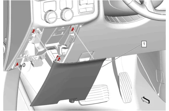
- Instrument Panel Lower Trim Panel Outer Filler (1) » Remove
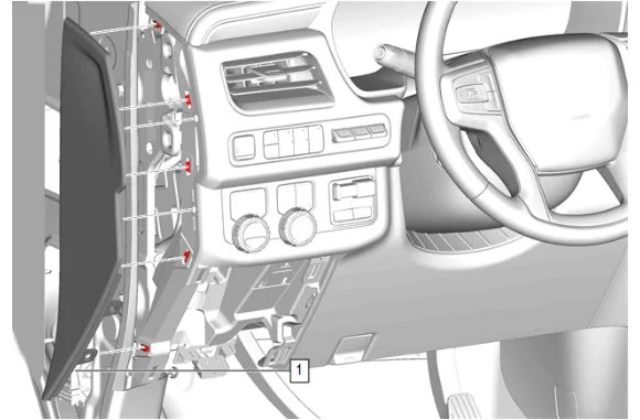
- Using a flat-bladed plastic trim tool, release the retaining clips.
- Instrument Panel Fuse Block Access Hole Cover (1) » Remove
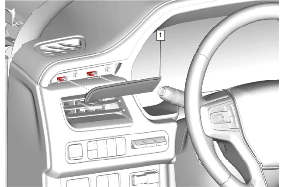
- Using a flat-bladed plastic trim tool, release the retaining clips.
- Instrument Panel Trim Plate Applique (1) » Remove
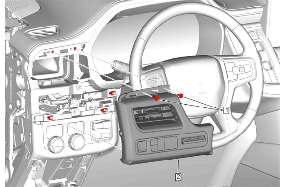
- Instrument Panel Trim Pad Bolt (1) » Remove [2x]
- Instrument Panel Trim Pad (2) » Remove
- Disconnect the electrical connectors.
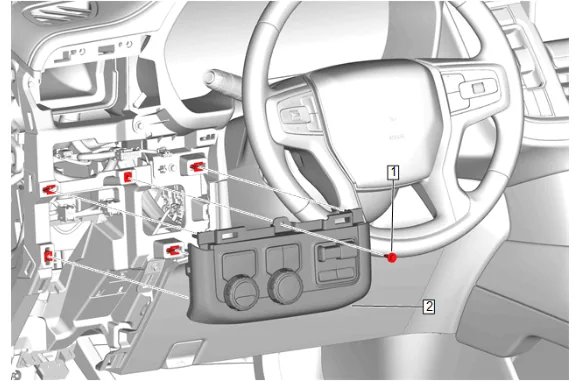
- Instrument Panel Switch Trim Plate Bolt (1) » Remove
- Disconnect the electrical connectors.
- Instrument Panel Switch Trim Plate (2) » Remove
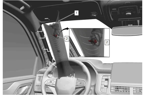
- Reposition the weatherstrip as necessary.
- Pull down the windshield garnish molding (1) rearwards to release the tether from the A pillar.
- Access the windshield garnish bolt (2) which is located on the backside of the windshield garnish molding (1) and secures the tether to the A pillar.
- Windshield Garnish Molding Bolt (2) » Remove
- Windshield Garnish Molding (1) » Remove
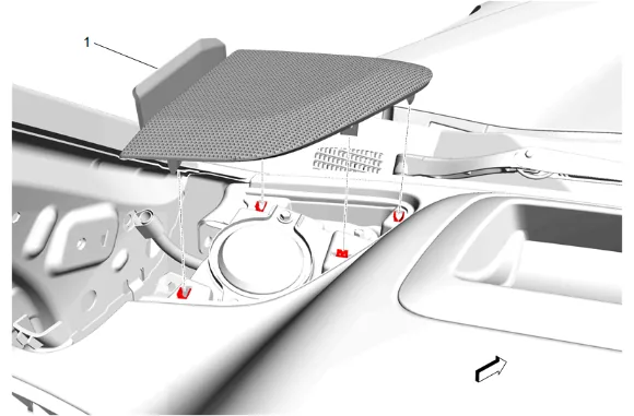
- Using a flat-bladed plastic trim tool, release the retaining clips.
- Radio Front Speaker Grille (1) » Remove
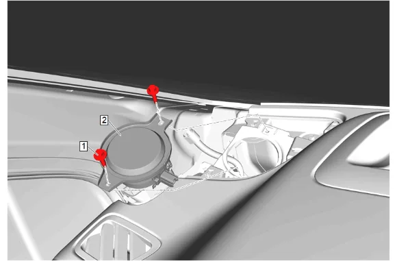
- Radio Front Speaker Bolt (1) » Remove [2x]
- Radio Front Speaker (2) » Remove
- Disconnect the electrical connector.
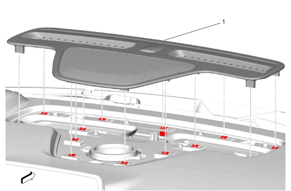
- Using a flat-bladed plastic trim tool, release the retaining clips.
- Disconnect the electrical connector.
- Instrument Panel Extension (1) » Remove
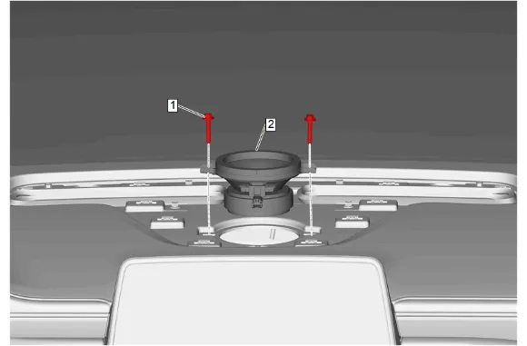
- Radio Front Center Speaker Bolt (1) » Remove [2x]
- Radio Front Center Speaker (2) » Remove
- Disconnect the electrical connector.
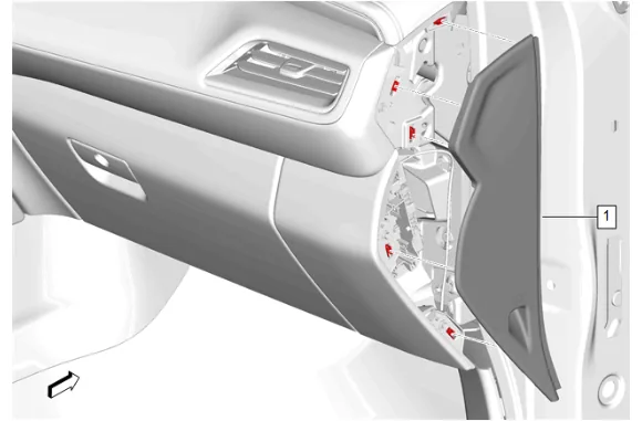
- Using a flat-bladed plastic trim tool, release the retaining clips.
- Instrument Panel Fuse Block Access Hole Cover (1) » Remove
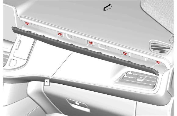
- Using a flat-bladed plastic trim tool, release the retaining clips.
- Instrument Panel Trim Plate Applique (1) » Remove
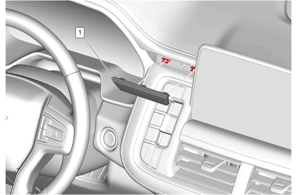
- Using a flat-bladed plastic trim tool, release the retaining clips.
- Instrument Panel Center Trim Plate Applique (1) » Remove
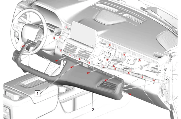
- Instrument Panel Upper Trim Panel Bolt (1) » Remove [6x]
- Using a flat-bladed plastic trim tool, release the retaining clips.
- Disconnect the electrical connector.
- Instrument Panel Trim Pad (2) » Remove
- Reposition the weatherstrip as necessary.
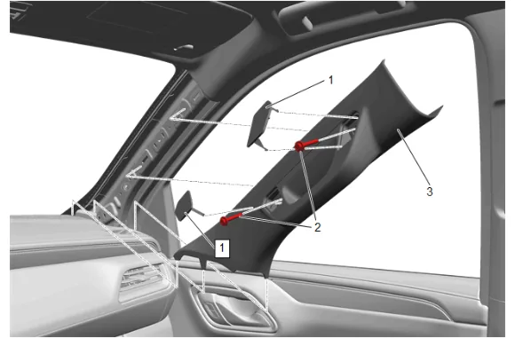
- Windshield Pillar Assist Handle Cover (1) » Remove [2x]
- Windshield Pillar Assist Handle Bolt (2) » Remove [2x]
- Windshield Garnish Molding (3) » Remove
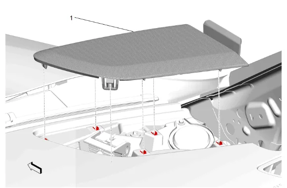
- Using a flat-bladed plastic trim tool, release the retaining clips.
- Radio Front Speaker Grille (1) » Remove
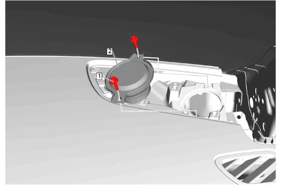
- Radio Front Speaker Bolt (1) » Remove [2x]
- Radio Front Speaker (2) » Remove
- Disconnect the electrical connector.
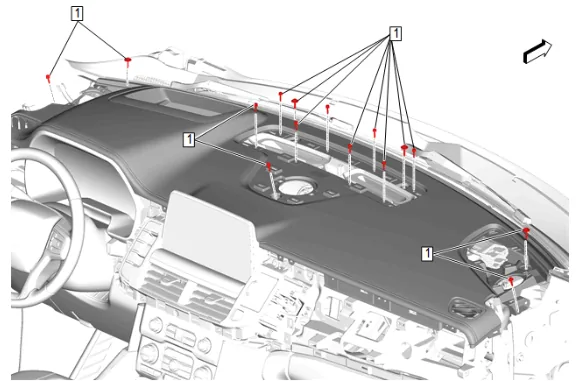
- Instrument Panel Upper Trim Panel Bolt (1) » Remove [15x]
- Disconnect the electrical connector.
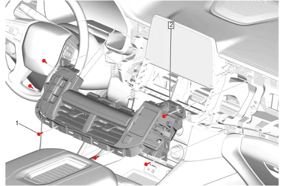
- Instrument Panel Center Trim Panel Bolt (1) » Remove [6x]
- Disconnect the electrical connectors.
- Instrument Panel Transmission Shift Opening Cover (2) » Remove
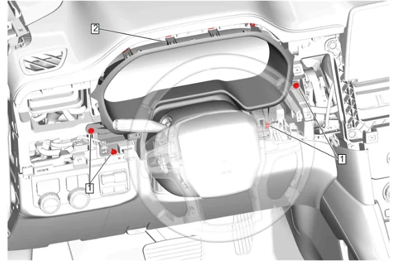
- Instrument Panel Cluster Trim Plate Bolt (1) » Loosen [4x]
- Using a flat-bladed plastic trim tool, release the retaining clips.
- Instrument Panel Cluster Trim Plate (2) » Loosen
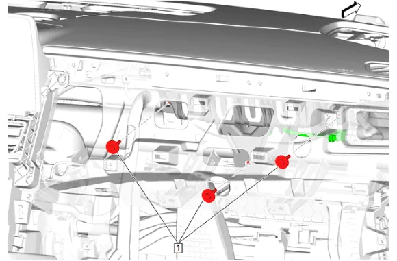
- Instrument Panel Airbag Bolt (1) » Remove [3x]
- Disconnect the electrical connector.
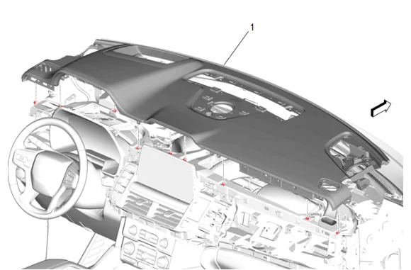
- Remove the instrument panel upper trim panel (1) with the aid of an assistant.
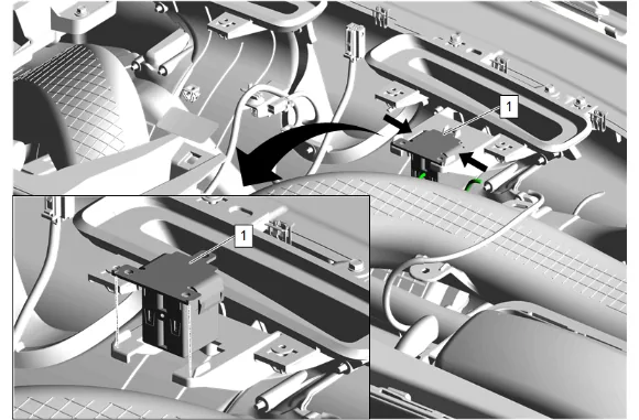
-
Release the retaining tabs.
-
Disconnect the electrical connector.
-
Auxiliary Wireless Communication Interface Antenna (1) » Remove Installation Procedure
-
Connect the electrical connector.
-
Auxiliary Wireless Communication Interface Antenna (1) » Install
-
Secure the retaining tabs.
-
Install the instrument panel upper trim panel (1) with the aid of an assistant.
-
Connect the electrical connector.
-
Instrument Panel Airbag Bolt (1) » Install and tighten [3x] — Fastener Specifications
-
Instrument Panel Cluster Trim Plate (2) » Install
-
Instrument Panel Cluster Trim Plate Bolt (1) » Tighten [4x] — Fastener Specifications
-
Connect the electrical connectors.
-
Instrument Panel Transmission Shift Opening Cover (2) » Install
-
Instrument Panel Center Trim Panel Bolt (1) » Install and tighten [6x] — Fastener Specifications
-
Instrument Panel Upper Trim Panel Bolt (1) » Install and tighten [15x] — Fastener Specifications
-
Connect the electrical connector.
-
Radio Front Speaker (2) » Install
-
Radio Front Speaker Bolt (1) » Install and tighten [2x] — Fastener Specifications
-
Radio Front Speaker Grille (1) » Install
-
Windshield Garnish Molding (3) » Install
-
Windshield Pillar Assist Handle Bolt (2) » Install and tighten [2x] — Fastener Specifications
-
Windshield Pillar Assist Handle Cover (1) » Install [2x]
-
Reposition the weatherstrip as necessary.
-
Connect the electrical connector.
-
Instrument Panel Trim Pad (2) » Install
-
Instrument Panel Upper Trim Panel Bolt (1) » Install and tighten [6x] — Fastener Specifications
-
Instrument Panel Center Trim Plate Applique (1) » Install
-
Instrument Panel Trim Plate Applique (1) » Install
-
Instrument Panel Fuse Block Access Hole Cover (1) » Install
-
Connect the electrical connector.
-
Radio Front Center Speaker (2) » Install
-
Radio Front Center Speaker Bolt (1) » Install and tighten [2x] — Fastener Specifications
-
Connect the electrical connector.
-
Instrument Panel Extension (1) » Install
-
Connect the electrical connector.
-
Radio Front Speaker (2) » Install
-
Radio Front Speaker Bolt (1) » Install and tighten [2x] — Fastener Specifications
-
Radio Front Speaker Grille (1) » Install
-
Windshield Garnish Molding Bolt (2) » Install and tighten — Fastener Specifications
-
Align the retaining clips with the slots in the A pillar and press the windshield garnish molding (1) into place.
-
Windshield Garnish Molding (1) » Install
-
Reposition the weatherstrip as necessary.
-
Connect the electrical connectors.
-
Instrument Panel Switch Trim Plate (2) » Install
-
Instrument Panel Switch Trim Plate Bolt (1) » Install and tighten — Fastener Specifications
-
Connect the electrical connectors.
-
Instrument Panel Trim Pad (2) » Install
-
Instrument Panel Trim Pad Bolt (1) » Install and tighten [2x] — Fastener Specifications
-
Instrument Panel Trim Plate Applique (1) » Install
-
Instrument Panel Fuse Block Access Hole Cover (1) » Install
-
Instrument Panel Lower Trim Panel Outer Filler (1) » Install
-
Enable the SIR System. SIR Disabling and Enabling