Power Steering Assist Motor Replacement
Single Use Fasteners and Components Electric Belt Drive Rack and Pinion Steering Gear Belt Power Steering Assist Motor Bolt [4x] Power Steering Assist Motor Seal @ Electric Belt Drive Rack and Pinion Steering Gear Power Steering Assist Motor Seal @ Power Steering Assist Motor Steering Gear Bolt [6x] Steering Gear Boot Clamp Special Tools Power Steering CH-22610 Keystone Clamp Pliers GE-50576–A Acoustic Belt Tension Tester Equivalent regional tools: Special Tools Steering Linkage CH-43631 Ball Joint Separator Equivalent regional tools: Special Tools Removal Procedure
- Disconnect the battery negative cable. Battery Negative Cable Disconnection and Connection
- Raise and support the vehicle. Lifting and Jacking the Vehicle
- Remove the front tire and wheel assemblies. Tire and Wheel Removal and Installation
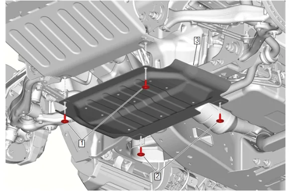
- {with RC1} Remove the underbody skid shield. 4.1. Underbody Skid Shield Bolt (1) » Remove [2x] 4.2. Underbody Splash Shield Bolt (2) » Remove [2x] 4.3. Underbody Skid Shield (3) » Remove
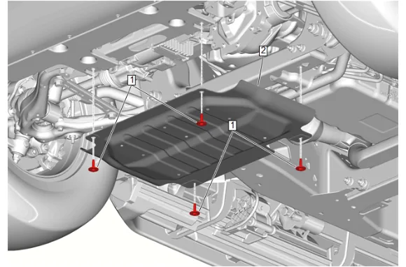
- {without RC1} Remove the underbody skid shield. 5.1. Underbody Skid Shield Bolt (1) » Remove [4x] 5.2. Underbody Skid Shield (2) » Remove
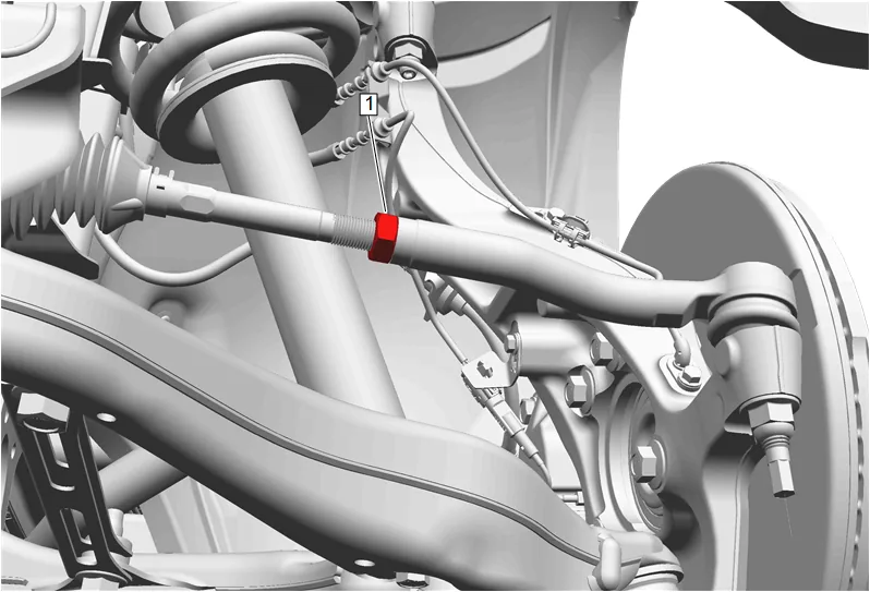
- Place match marks on the right side steering linkage inner tie rod nut (1) and the right side steering linkage inner tie rod.
- Steering Linkage Inner Tie Rod Nut - Right Side (1) » Loosen
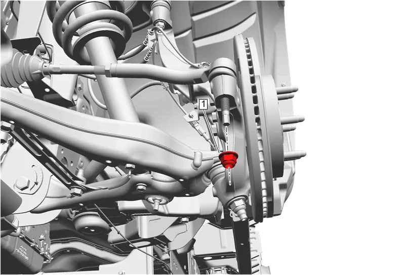
- Steering Linkage Outer Tie Rod Nut - Right Side (1) » Remove
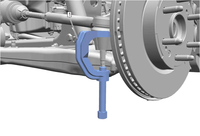
- Using CH-43631 Ball Joint Separator (1), remove the right side steering linkage outer tie rod from the steering knuckle.
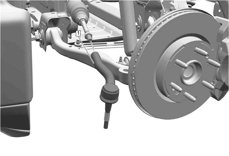
- Steering Linkage Outer Tie Rod - Right Side (1) » Remove
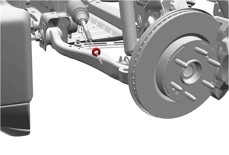
- Steering Linkage Inner Tie Rod Nut - Right Side (1) » Remove
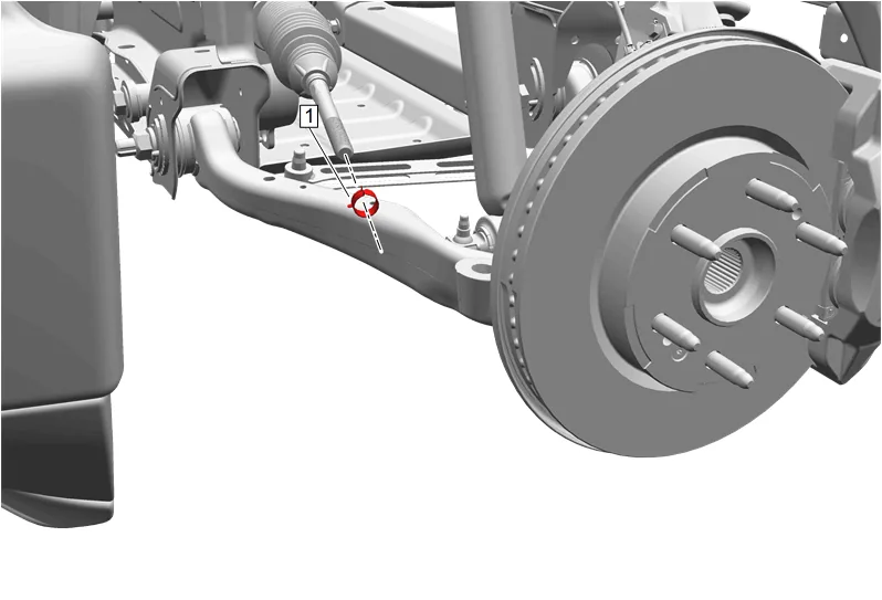
- Steering Gear Boot Outer Clamp - Right Side (1) » Remove
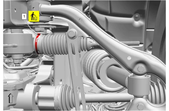
- Steering Gear Boot Clamp - Right Side (1) » Remove and DISCARD
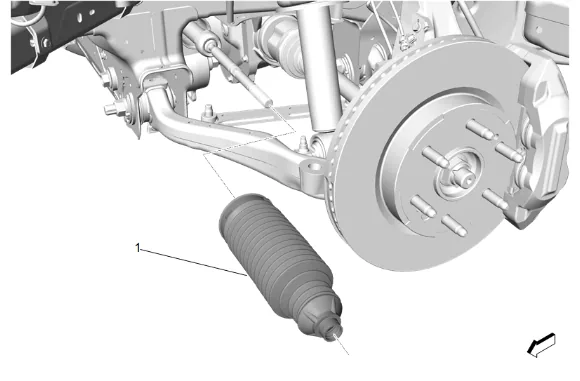
- Steering Gear Boot - Right Side (1) » Remove
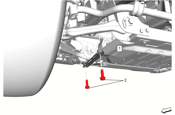
- Front Lower Control Arm Bracket Bolt (2) » Remove [2x]
- Front Lower Control Arm Brace - Right Side (1) » Remove
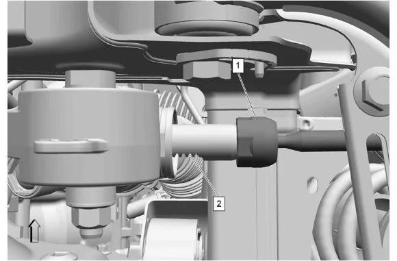
- Cover the electric belt drive rack and pinion steering gear bar (2) with a clean shop towel.
- Hold the electric belt drive rack and pinion steering gear bar (2) with a non-serrated adjustable wrench.
- Using a universal inner tie rod wrench, loosen the right side steering linkage inner tie rod (1).
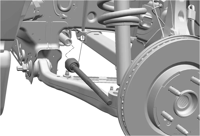
- Steering Linkage Inner Tie Rod - Right Side (1) » Remove
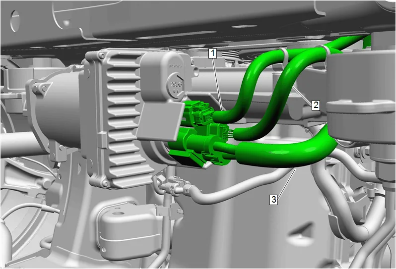
- Disconnect the power steering wiring harness extension (1) and reposition.
- Disconnect the torque sensor power steering control module wiring harness (2) and reposition.
- Disconnect the power steering control module wiring harness (3) and reposition.
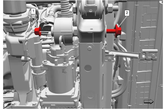
- Steering Gear Nut - Right Side (1) » Remove
- Steering Gear Bolt - Right Side (2) » Remove
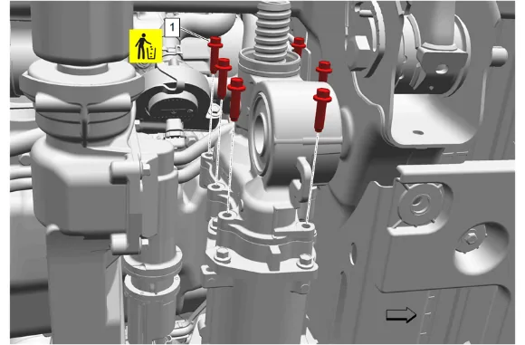
- Steering Gear Bolt (1) » Remove and DISCARD [6x]
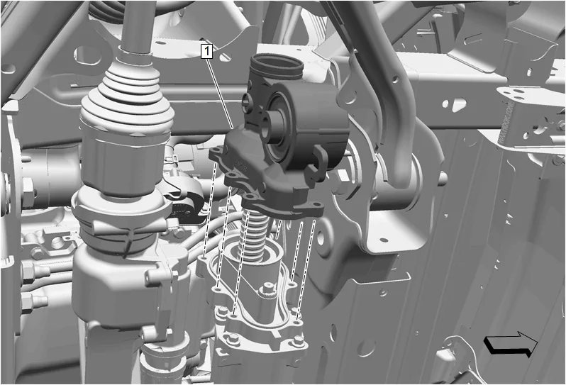
- Remove the power steering assist motor belt tension access cover (1).
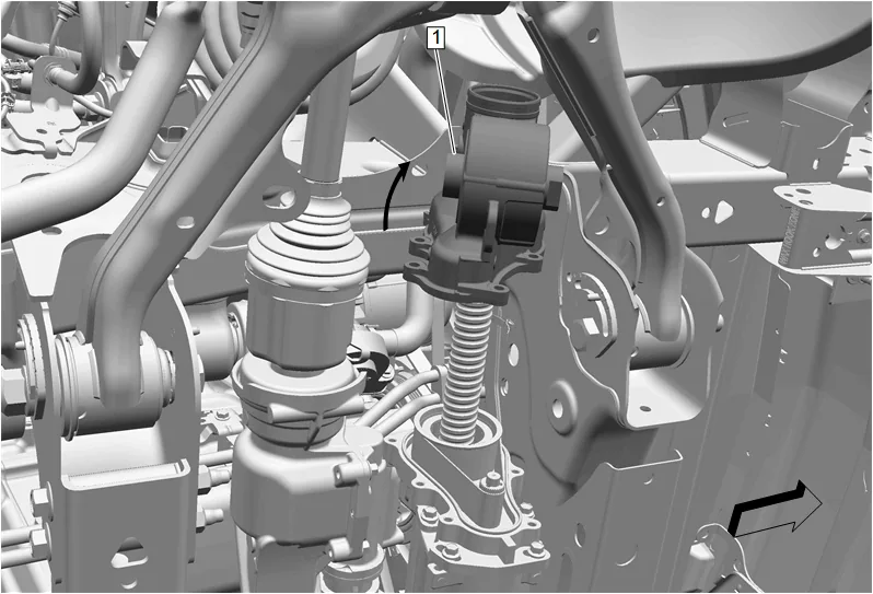
- Rotate the power steering assist motor access cover (1) clockwise to complete the removal.
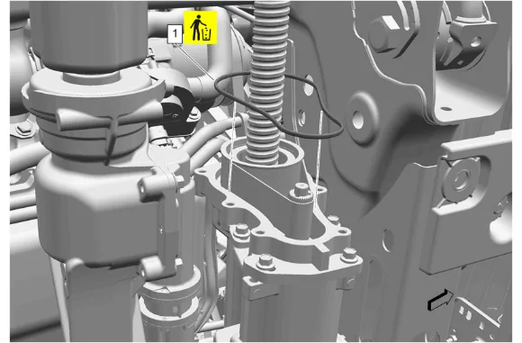
- Power Steering Assist Motor Seal (1) @ Electric Belt Drive Rack and Pinion Steering Gear » Remove and DISCARD
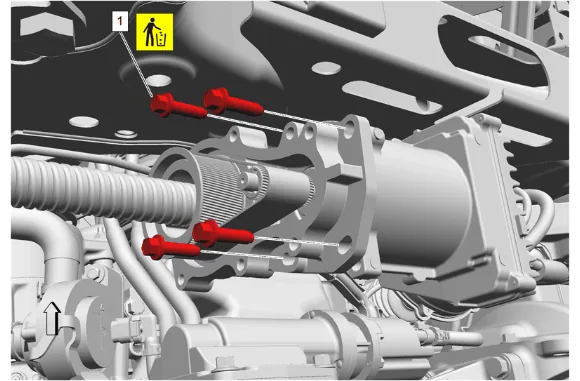
- Power Steering Assist Motor Bolt (1) » Remove and DISCARD (4x)
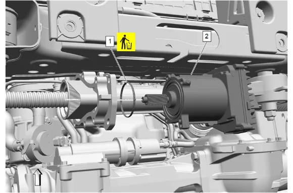
- Power Steering Assist Motor (2) » Remove
- Power Steering Assist Motor Seal (1) @ Power Steering Assist Motor » Remove and DISCARD
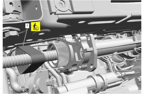
- Remove the electric belt drive rack and pinion steering gear belt (1) and DISCARD.
- Inspect the electric belt drive rack and pinion steering gear housing and the power steering assist motor shaft for signs of water intrusion or corrosion.
- If signs of water intrusion or corrosion are present, replace the electric belt drive rack and pinion steering gear.
- Inspect the power steering rack bar and electric belt drive rack and pinion steering gear housing cover to ensure it is free from debris.
-
Using a commercially available abrasive cleaning pad with a grit ranging between 320 and 400, clean the power steering assist motor sealing surface removing all corrosion from the surface area.
-
Using low pressured compressed air, blow any debris from the electric belt drive rack and pinion steering gear belt cavity. Do NOT use any cleaning fluid within the cavity as cleaning fluid could remove the grease on the rack bar located inside the cavity. Installation Procedure
-
Electric Belt Drive Rack and Pinion Steering Gear Belt (1) » Install NEW
- Apply a thin layer of grease to the power steering assist motor seal. Adhesives, Fluids, Lubricants, and Sealers
- Power Steering Assist Motor Seal (1) @ Power Steering Assist Motor » Install NEW
- Fill the outer channel of the power steering assist motor with grease. Adhesives, Fluids, Lubricants, and Sealers
- Install the power steering assist motor (2) into the electric belt drive rack and pinion steering gear while positioning the electric belt drive rack and pinion steering gear belt onto the power steering assist motor pulley.
- Turn the power steering assist motor clockwise to apply a small amount of tension to the electric belt drive rack and pinion steering gear belt and install the 4 NEW power steering assist motor bolts (1) in small, equal increments until all the bolts are tightened by hand.
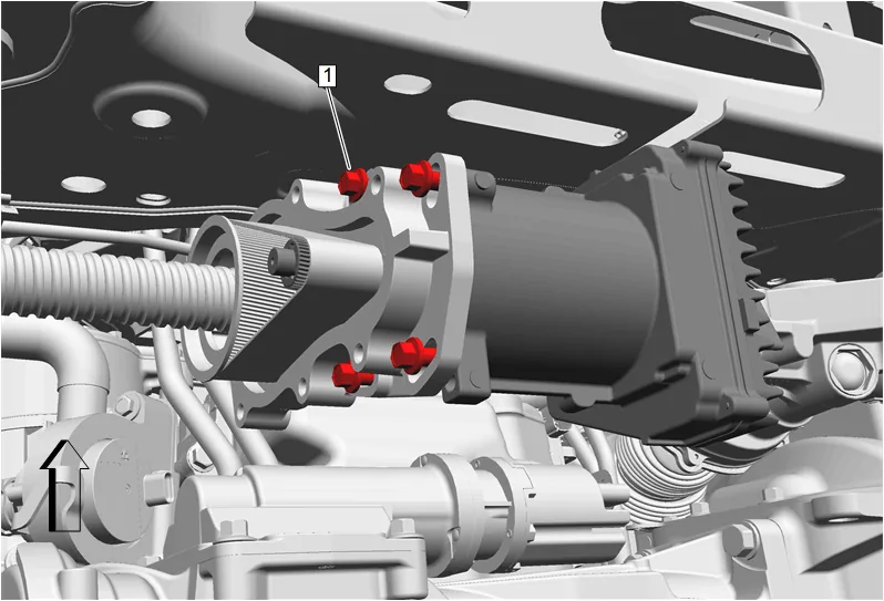
- Power Steering Assist Motor Pivot Bolt (1) » Tighten — Fastener Specifications
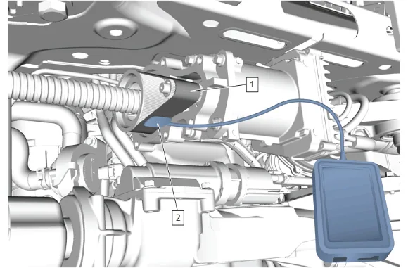
- Place the body of the GE-50576–A Acoustic Belt Tension Tester (2) on a flat surface or secure it to the electric belt drive rack and pinion steering gear housing.
- Position the microphone of the GE-50576-A Acoustic Belt Tension Tester (2) 6 mm (0.25 in) from the electric belt drive rack and pinion steering gear belt (1).
- Use an allen wrench or finger to strum the steering gear belt at the center location between the two pulleys three times to get an average belt tension reading.
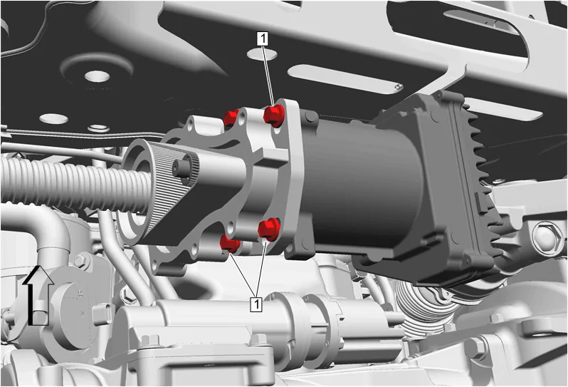
- If the average electric belt drive rack and pinion steering gear belt tension reading is between 245 Hz - 265 Hz, tighten the 3 remaining power steering assist motor bolts (1) and continue with the procedure. Fastener Specifications
- After all of the power steering assist motor bolts have been tightened to specification, repeat step 11 to ensure the belt tension frequency remains between 245 Hz - 265 Hz.
-
If the average electric belt drive rack and pinion steering gear belt tension reading is above or below 245 Hz - 265 Hz, perform the following steps: 13.1. Loosen the power steering assist motor pivot bolt and rotate the power steering assist motor clockwise to increase the tension or counterclockwise to reduce the tension on the belt. 13.2. Tighten the power steering assist motor pivot bolt and test the average belt tension three times. Fastener Specifications 13.3. If the average belt tension reading is between 245 Hz - 265 Hz, tighten the 3 power steering assist motor bolts (1). Fastener Specifications 13.4. Continue the process until the average belt tension reading is between 245 Hz - 265 Hz. Once the correct tension is achieved, tighten the 4 power steering assist motor bolts and continue with the procedure. Fastener Specifications
-
Remove the GE-50576-A Acoustic Belt Tension Tester.
-
Apply a thin layer of grease to the power steering assist motor seal (1) at the electric belt drive rack and pinion steering gear. Adhesives, Fluids, Lubricants, and Sealers
-
Power Steering Assist Motor Seal @ Electric Belt Drive Rack and Pinion Steering Gear (1) » Install NEW
-
Rotate the power steering assist motor belt tension access cover (1) clockwise to begin the installation.
-
Install the power steering assist motor belt tension access cover (1).
-
Steering Gear Bolt (1) » Install NEW and tighten in sequence [6x] — Fastener Specifications
-
Steering Gear Nut - Right Side (1) » Install
-
Steering Gear Bolt - Right Side (2) » Install and tighten — Fastener Specifications
- Connect the power steering wiring harness extension (1).
- Connect the torque sensor power steering control module wiring harness (2).
- Connect the power steering control module wiring harness (3).
- Front Lower Control Arm Brace - Right Side (1) » Install
- Front Lower Control Arm Bracket Bolt (2) » Install and tighten [2x] — Fastener Specifications
- Steering Linkage Inner Tie Rod - Right Side (1) » Install
- Cover the electric belt drive rack and pinion steering gear bar (2) with a clean shop towel.
- Hold the electric belt drive rack and pinion steering gear bar (2) with a non-serrated adjustable wrench.
- Using a universal inner tie rod wrench, tighten the right side steering linkage inner tie rod (1). Fastener Specifications
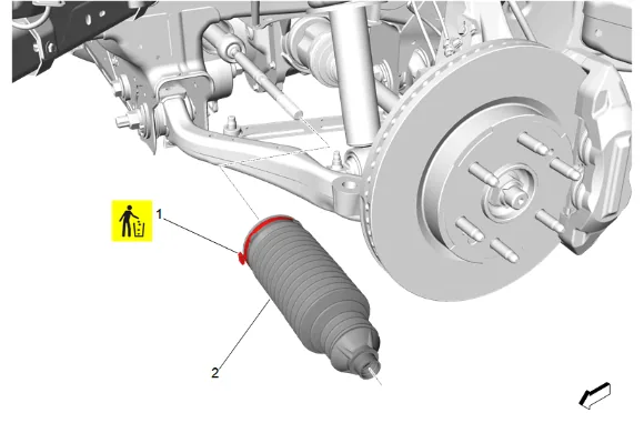
- Position a NEW steering gear boot clamp (1) on the steering gear boot (2).
- Steering Gear Boot - Right Side (2) » Install
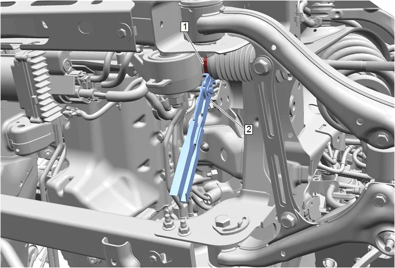
- Steering Gear Boot Inner Clamp - Right Side (1) » Tighten - use CH-22610 Keystone Clamp Pliers (2)
- Steering Gear Boot Outer Clamp - Right Side (1) » Install
- Install the right side steering linkage inner tie rod nut (1) until aligned with the previously placed matched mark on the right side steering linkage inner tie rod.
- If reusing the steering linkage outer tie rod (1), add a small amount of grease on the lip of the rubber boot seal to prevent twisting or deforming of the boot. Do NOT apply grease to the ball joint stud. Adhesives, Fluids, Lubricants, and Sealers
- Steering Linkage Outer Tie Rod - Right Side (1) » Install
- Steering Linkage Outer Tie Rod Nut - Right Side (1) » Install and tighten — Fastener Specifications
-
Tighten the right side steering linkage inner tie rod nut (1) during the front toe adjustment procedure.
-
{without RC1} Install the underbody skid shield. 40.1. Underbody Skid Shield (2) » Install 40.2. Underbody Skid Shield Bolt (1) » Install and tighten [4x] — Fastener Specifications
- {with RC1} Install the underbody skid shield. 41.1. Underbody Skid Shield (3) » Install 41.2. Underbody Splash Shield Bolt (2) » Install and tighten [2x] — Fastener Specifications 41.3. Underbody Skid Shield Bolt (1) » Install and tighten [2x] — Fastener Specifications
- Install the front tire and wheel assemblies. Tire and Wheel Removal and Installation
- Lower the vehicle.
- Connect the battery negative cable. Battery Negative Cable Disconnection and Connection
- Perform the necessary programming and setup procedure: Control Module References
- Measure and adjust the front toe. Wheel Alignment - Steering Wheel Angle and/or Front Toe Adjustment