Brake Rotor Assembled Lateral Runout Correction - Indexing
Brake Rotor Assembled Lateral Runout Correction - Indexing Special Tools CH-45101-100 Conical Brake Rotor Washers For equivalent regional tools, refer to Special Tools.
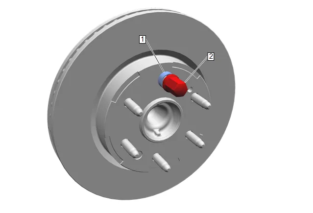
- Remove the CH-45101-100 Conical Brake Rotor Washers and the lug nuts that were installed during the assembled LRO measurement procedure.
- Inspect the mating surface of the hub/axle flange and the brake rotor to ensure that there are no foreign particles or debris remaining.
- Index the brake rotor in a different orientation to the hub/axle flange.
- Hold the rotor firmly in place against the hub/axle flange and install one of the CH-45101-100 Conical Brake Rotor Washers (1) and one lug nut (2) onto the upper-most wheel stud.
- Continue to hold the rotor secure and tighten the lug nut firmly by hand.
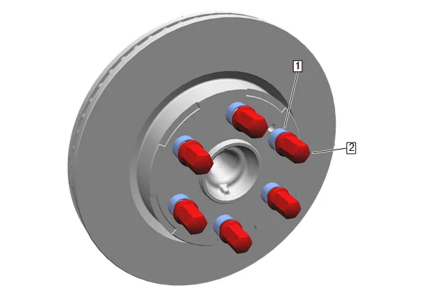
- Install the remaining CH-45101-100 Conical Brake Rotor Washers and lug nuts onto the wheel studs and tighten the nuts firmly by hand in a star-pattern.
- Tighten the lug nuts in a star-pattern to specification, in order to properly secure the rotor. Tire and Wheel Removal and Installation
- Measure the assembled LRO of the brake rotor. Brake Rotor Assembled Lateral Runout Measurement
- Compare the amount of change between this measurement and the original measurement.
- If this measurement is within specifications, proceed to step 14.
- If this measurement still exceeds specifications, repeat steps 1–9 until the best assembled LRO measurement is obtained.
- Matchmark the final location of the rotor to the wheel studs if the orientation is different than it was originally.
- If the brake rotor assembled LRO measurement still exceeds the maximum allowable specification, perform Brake Rotor Assembled Lateral Runout Correction.
- If the brake rotor assembled LRO is within specification, install the brake caliper and depress the brake pedal several times to secure the rotor in place before removing the CH-45101-100 Conical Brake Rotor Washers and the lug nuts.