Inflatable Restraint Module Handling and Scrapping
Special Tools EL-38826 SIR Deployment Harness EL-38826–200 SIR Deployment Harness Jumper EL-39401-B SIR Deployment Fixture For equivalent regional tools, refer to Special Tools. Live and Undeployed Inflator Module
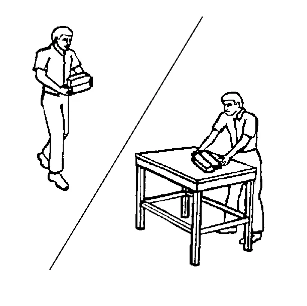
Take special care when handling or storing an undeployed inflator module. An inflator module deployment produces a rapid generation of gas. This may cause the inflator module, or an object in front of the inflator module, to project through the air in the event of an unlikely deployment. Dual Stage Inflator Module Dual stage inflator modules have 2 deployment stages. If stage 1 was used to deploy a dual stage inflator module, stage 2 may still be active. Therefore, a deployed dual stage inflator module must be treated as an active module. If disposal of a dual stage module is required, both deployment loops must be energized to deploy the air bag. Scrapping Procedure During the course of a vehicles useful life, certain situations may arise which will require the disposal of a live and undeployed inflator module. Do NOT dispose a live and undeployed inflator module through normal disposal channels until the inflator module has been deployed. Do not deploy the inflator module in the following situations: After replacement of an inflator module under warranty—the inflator module may need to be returned undeployed to the manufacturer. If the vehicle is the subject of a Product Liability report, GM-1241, related to the SIR system and is subject to a preliminary investigation—do NOT alter the SIR system in any manner. If the vehicle is involved in a campaign affecting the inflator modules—follow the instructions in the Campaign Service Bulletin for proper SIR handling procedures. Deployment Procedures
- Turn OFF the ignition.
- Remove the ignition key.
- Disconnect negative battery terminal. Refer to: SIR Disabling and Enabling
- Put on safety glasses and hearing protection.
- Remove the inflator module. Refer to the relevant airbag replacement procedure.
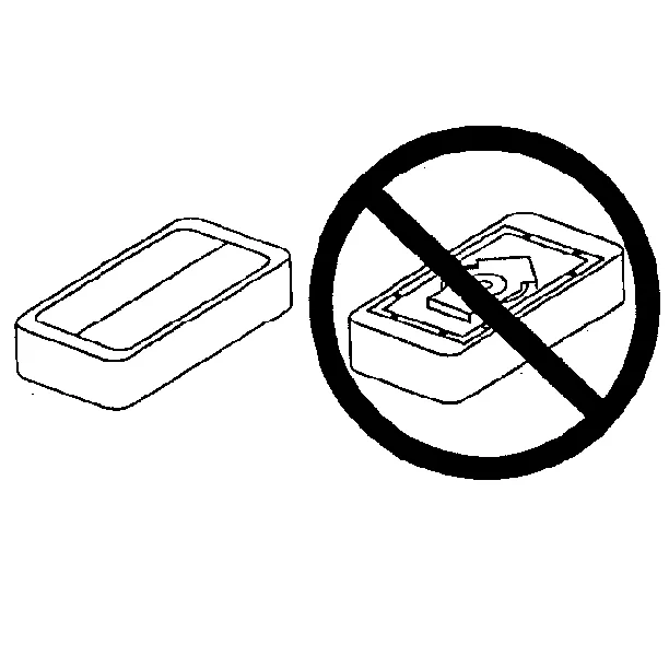
- Place the inflator module on a work bench, with the vinyl trim cover facing up and away from the surface.
- Clear a space on the ground about 4 m (13.1 ft) in diameter for deployment of the inflator module or deployment fixture. If possible, use a paved, outdoor location free of activity. Otherwise, use a space free of activity on the shop floor. Ensure you have sufficient ventilation.
- Clear the area of loose or flammable objects.
- If you are deploying a steering wheel inflator module, place the inflator module in the center of the space.
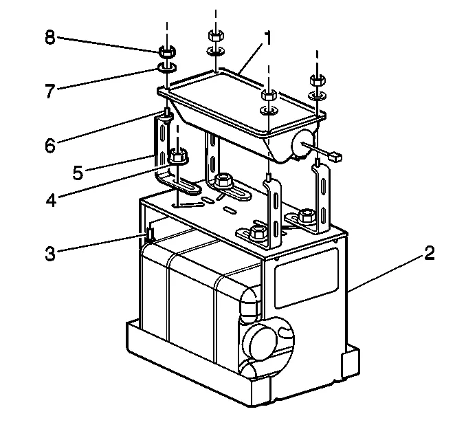
- When deploying an I/P inflator module, perform the following instructions: 10.1. Place the J 39401-B SIR deployment fixture in the center of the cleared area. 10.2. Fill the deployment fixture with water or sand. 10.3. Using the proper nuts and bolts, mount the I/P module (1) to the deployment fixture (2), with the vinyl trim facing up. 10.4. Securely tighten all fasteners that hold the I/P module (1) to the deployment fixture (2).
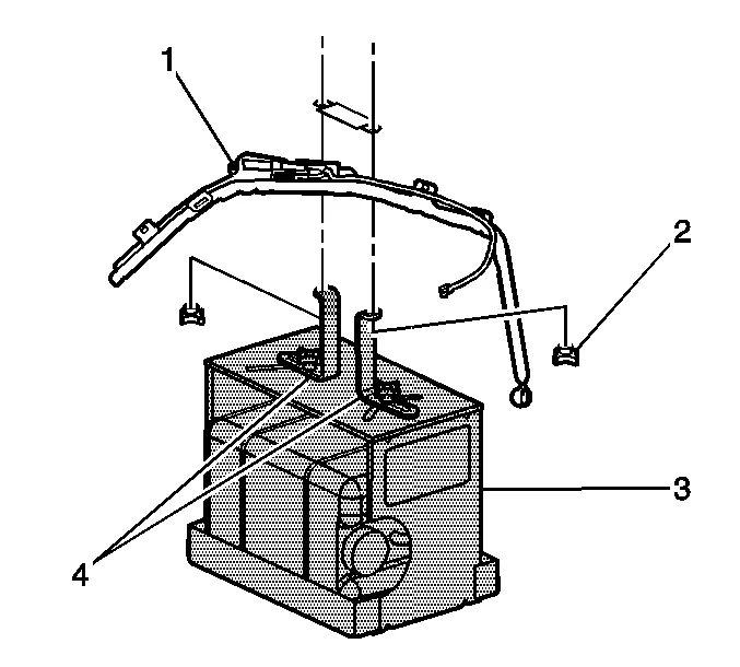
- When deploying a roof rail module, perform the following instructions: 11.1. Place the J 39401-B SIR deployment fixture (3) in the center of the cleared area. 11.2. Fill the deployment fixture with water or sand to provide sufficient stabilization of fixture during deployment. 11.3. Adjust and secure the fixture arms (4) to the deployment fixture (3), using the proper nuts and bolts. 11.4. Attach the roof rail module in the deployment fixture and securely tighten all fasteners.
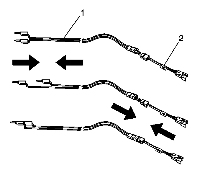
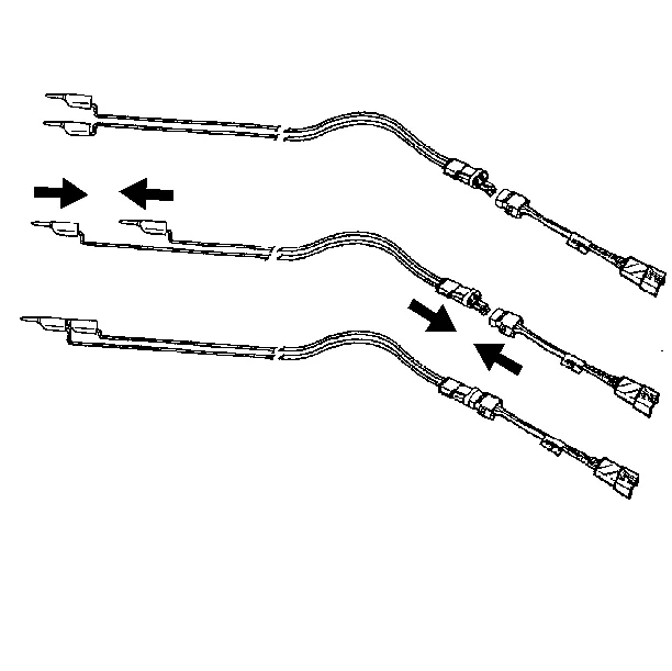
- Inspect the SIR deployment harness and the appropriate pigtail adapter (2) for damage.
- Short the 2 SIR deployment harness leads (1) together using one banana plug seated into the other.
- Connect the appropriate pigtail adapter (2) to the SIR deployment harness (1).
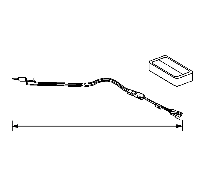
- Extend the SIR deployment harness and adapter to the full length from the deployment fixture or area.
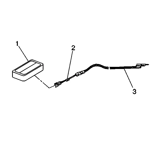
- Connect the inflator module (1) to the adapter (2) on the SIR deployment harness (3).
- Clear the area of people.
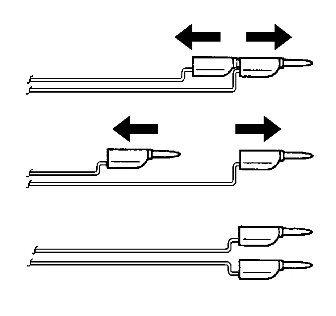
- Separate the 2 banana plugs on the SIR deployment harness that were shorted together earlier in the procedure.
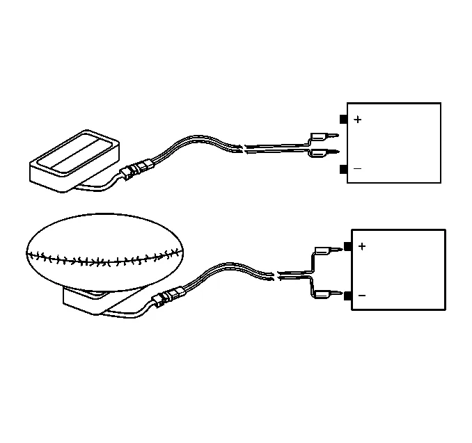
- Place a 12-volt minimum/2-amp minimum power source, such as a vehicle battery, near the shorted end of the harness.
- Connect the SIR deployment harness wires to the power source. Deployment of the inflator module will occur when contact is made.
- Disconnect the SIR deployment harness from the power source after the inflator module deploys.
- If the inflator module did not deploy, disconnect the adapter and discontinue the procedure and contact the Technical Assistance Group. If deployment was successful, proceed to the following steps.
- Seat one banana plug into the other in order to short the deployment harness leads.
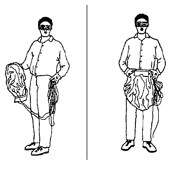
- Put on a pair of shop gloves.
- Disconnect the pigtail adapter from the inflator module as soon as possible.
- Inspect the pigtail adapter and the SIR deployment harness. Replace as needed.
- Dispose of the deployed inflator module through normal refuse channels.
- Wash your hands with a mild soap. Deployment Inside Vehicle – Vehicle Scrapping Procedure Deploy the inflator modules inside of the vehicle when destroying the vehicle or when salvaging the vehicle for parts. This includes, but is not limited to, the following situations: The vehicle has completed all useful life. Irreparable damage occurred to the vehicle in a non-deployment type accident. Irreparable damage occurred to the vehicle during a theft. The vehicle is being salvaged for parts to be used on a vehicle with a different VIN, as opposed to rebuilding as the same VIN.
- Lower the driver and passenger windows.
- Turn the ignition switch to the OFF position and remove the ignition key.
- Check that all inflator modules which will be deployed are mounted securely. Driver inflator module is secured to the steering wheel. Passenger inflator module is secured to the instrument panel. Left roof rail inflator module is secured to the left roof rail. Right roof rail inflator module is secured to the right roof rail.
- Put on safety glasses and hearing protection.
- Disconnect negative battery terminal. Refer to: SIR Disabling and Enabling
- Remove all loose objects from the front seats.
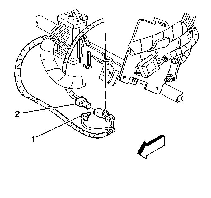
- Disconnect the steering wheel module yellow connector (1) from vehicle harness yellow connector (2).
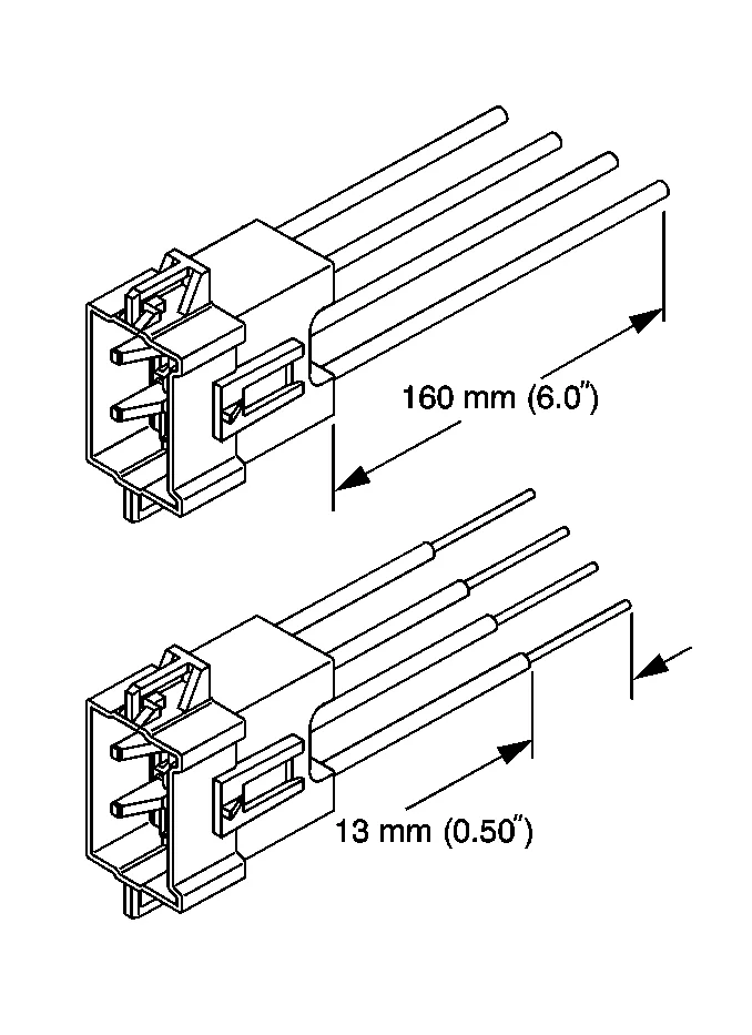
- Cut the yellow harness connector out of the vehicle, leaving at least 16 cm (6 in) of wire at the connector.
- Strip 13 mm (0.5 in) of insulation from each of the connector wire leads.
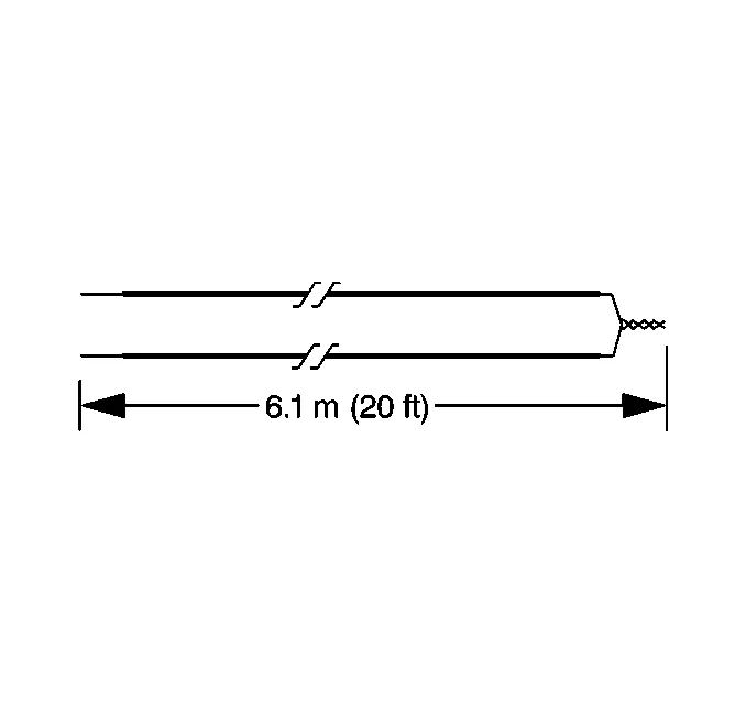
- Cut two 6.1 m (20 ft) deployment wires from a 0.8 mm (18 gauge) or thicker multi-strand wire. Use these wires to fabricate the driver deployment harness.
- Strip 13 mm (0.5 in) of insulation from both ends of the wires.
- Twist together one end from each of the wires in order to short the wires. Deployment wires shall remain shorted, and not connected to a power source until you are ready to deploy the inflator module.
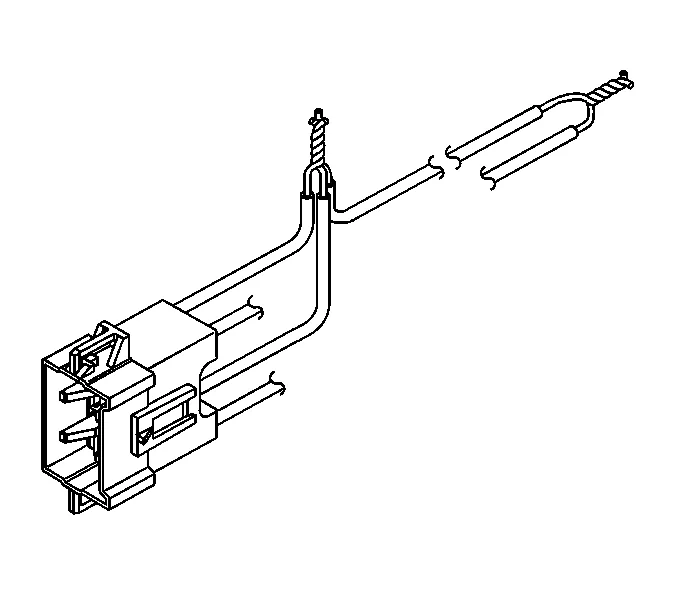
- Twist together the 2 connector wire leads from the high circuits from both stages of the steering wheel module, to one set of deployment wires. Refer to Master Electrical Component List in order to determine the correct circuits.
- Inspect that the 3-wire connection is secure.
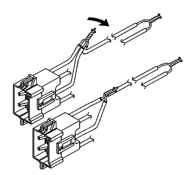
- Bend flat the twisted connection.
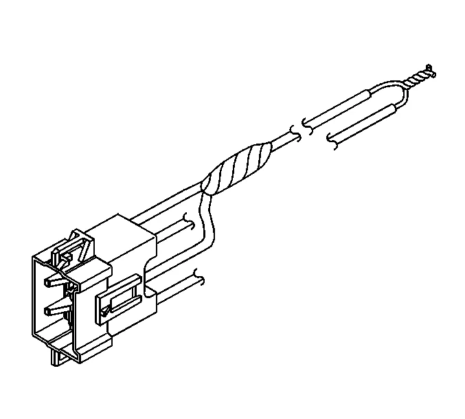
- Secure and insulate the 3-wire connection to the deployment harness using electrical tape.
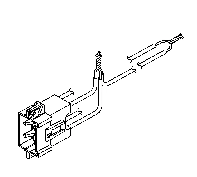
- Twist together the 2 connector wire leads from the low circuits from both stages of the steering wheel module, to one set of deployment wires. Refer to Master Electrical Component List in order to determine the correct circuits.
- Inspect that the 3-wire connection is secure.
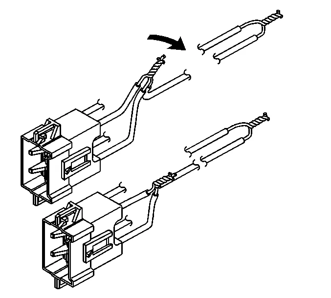
- Bend flat the twisted connection.
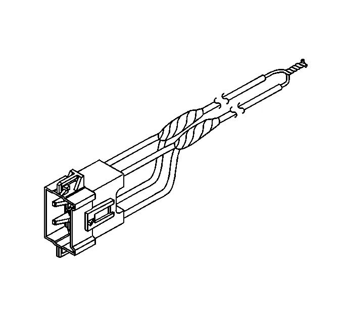
- Secure and insulate the 3-wire connection to the deployment harness using electrical tape.
- Connect the deployment harness to the connector on the steering wheel module.
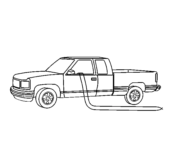
- Route the deployment harness out of the driver side of the vehicle.
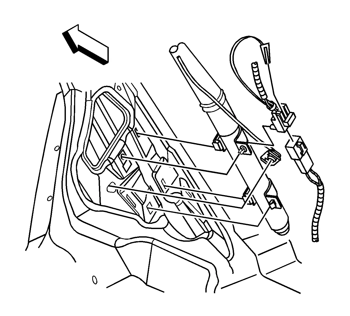
- Disconnect the yellow left roof rail harness connector from the vehicle harness connector.
-
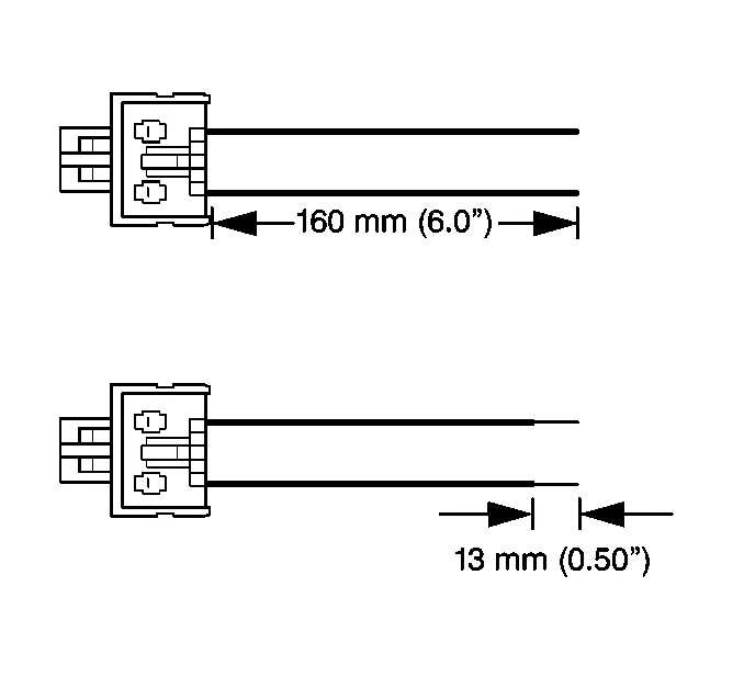
Cut the harness connector out of the vehicle, leaving at least 16 cm (6 in) of wire at the connector.
-
Strip 13 mm (0.5 in) of insulation from each of the connector wire leads.
-
Cut two 6.1 m (20 ft) deployment wires from a 0.8 mm (18 gauge) or thicker multi-strand wire. These wires will be used to fabricate the roof rail air bag deployment harness.
-
Strip 13 mm (0.5 in) of insulation from both ends of the wires.
-
Twist together one end from each of the wires in order to short the wires.
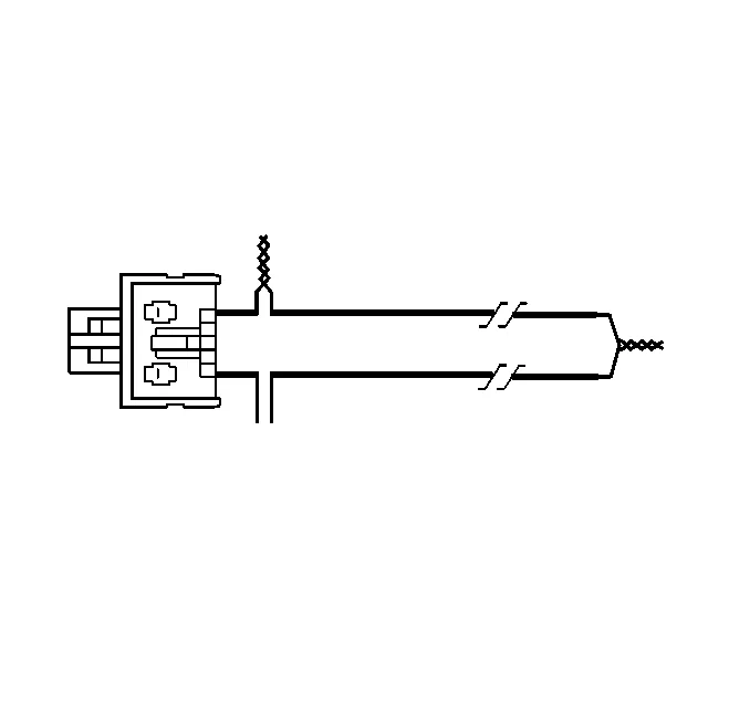
- Twist together one connector wire lead to one deployment wire.
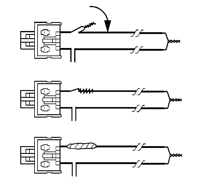
- Bend flat the twisted connection.
- Secure and insulate the connection using electrical tape.
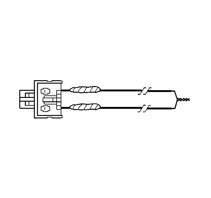
-
Twist together, bend, and tape the remaining connector wire lead to the remaining deployment wire.
-
Connect the deployment harness to the yellow connector of the roof rail module.
-
Route the deployment harness out of the driver side of the vehicle.
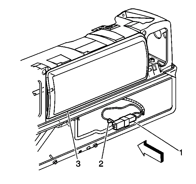
- Disconnect the I/P module yellow harness connector (1) from the vehicle harness connector (2).
-
Cut the yellow harness connector out of the vehicle, leaving at least 16 cm (6 in) of wire at the connector.
-
Strip 13 mm (0.5 in) of insulation from each of the connector wire leads.
-
Cut two 6.1 m (20 ft) deployment wires from a 0.8 mm (18 gauge) or thicker multi-strand wire. These wires will be used to fabricate the passenger deployment harness.
-
Strip 13 mm (0.5 in) of insulation from both ends of the wires.
-
Twist together one end from each of the wires in order to short the wires.
-
Twist together the 2 connector wire leads from the high circuits from both stages of the I/P module to one set of deployment wires. Refer to Master Electrical Component List in order to determine the correct circuits.
-
Inspect that the 3-wire connection is secure.
-
Bend flat the twisted connection.
-
Secure and insulate the 3-wire connection to the deployment harness using electrical tape.
-
Twist together the 2 connector wire leads from the low circuits from both stages of the I/P module to one set of deployment wires. Refer to Master Electrical Component List in order to determine the correct circuits.
-
Inspect that the 3-wire connection is secure.
-
Bend flat the twisted connection.
-
Secure and insulate the 3-wire connection to the deployment harness using electrical tape.
-
Connect the deployment harness to the I/P module in-line connector.
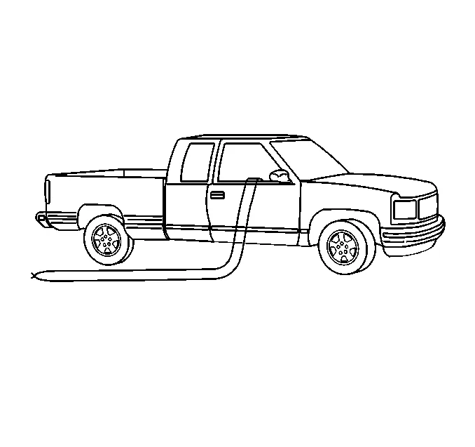
-
Route the deployment harness out of the passenger side of the vehicle.
-
Disconnect the yellow harness connector to the right roof rail air bag from the vehicle harness connector.
-
Cut the harness connector out of the vehicle, leaving at least 16 cm (6 in) of wire at the connector.
-
Strip 13 mm (0.5 in) of insulation from each of the connector wire leads.
-
Cut two 6.1 m (20 ft) deployment wires from a 0.8 mm (18 gauge) or thicker multi-strand wire. These wires will be used to fabricate the roof rail module deployment harness.
-
Strip 13 mm (0.5 in) of insulation from both ends of the wires.
-
Twist together one end from each of the wires in order to short the wires.
-
Twist together one connector wire lead to one deployment wire.
-
Bend flat the twisted connection.
-
Secure and insulate the connection using electrical tape.
-
Twist together, bend, and tape the remaining connector wire lead to the remaining deployment wire.
-
Connect the deployment harness to the roof rail module yellow connector.
-
Route the deployment harness out of the passenger side of the vehicle.
-
Completely cover the windshield and the front door window openings with a drop cloth.
-
Stretch to the full length all of the deployment harness wires on the right side of the vehicle.
-
Deploy each deployment loop one at a time.
-
Place a power source, 12 V minimum/2 A minimum, such as a vehicle battery, near the shorted end of the harnesses.
-
Separate one set of wires and touch the wire ends to the power source in order to deploy the selected inflator module.
-
Disconnect the deployment harness from the power source and twist the wire ends together.
-
Continue the same process with the remaining deployment harnesses.
-
Stretch to the full length all of the deployment harness wires on the left side of the vehicle.
-
Deploy each deployment loop one at a time.
-
Place a power source, 12 V minimum/2 A minimum, such as a vehicle battery, near the shorted end of the harnesses.
-
Separate one set of wires and touch the wires ends to the power source in order to deploy the selected inflator modules.
-
Disconnect the deployment harness from the power source and twist the wire ends together.
-
Continue the same process with the remaining deployment harnesses.
-
Remove the drop cloth from the vehicle.
-
Disconnect all harnesses from the vehicle.
-
Discard the harnesses.
-
Scrap the vehicle in the same manner as a non-SIR equipped vehicle.
-
If one or all of the inflator modules did not deploy, use the relevant airbag replacement procedure to remove the undeployed modules from the vehicle.