Valve Lifter Replacement - Left Side (L84)
Single Use Fasteners and Components Accessory Drive Primary Belt Cylinder Head Bolt - M12 x 134 [9x] Cylinder Head Bolt - M12 x 102 Cylinder Head Gasket Exhaust Manifold Bolt [5x] Exhaust Manifold Gasket Exhaust System Seal Fuel Feed Intermediate Pipe [2x] Intake Manifold Gasket [8x] Oil Filter Valve Rocker Arm Cover Gasket Special Tools EN-47909 Injector Bore and Sleeve Cleaning Kit EN-51767 Stretchy Belt Installer J-8089 Carbon Removal Brush J-9666 Valve Spring Tester Equivalent regional tools: Special Tools
- Relieve the fuel system pressure. Fuel Pressure Relief
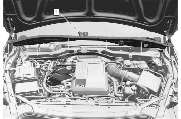
- Plenum Front Panel Outer Reinforcement (1) » Remove — Plenum Front Panel Outer Reinforcement Removal and Installation
- Drain the cooling system. Cooling System Draining and Filling
- Engine Oil and Oil Filter » Remove and DISCARD — Engine Oil and Oil Filter Replacement
- Front Wheelhouse Liner - Left Side » Remove — Front Wheelhouse Liner Replacement
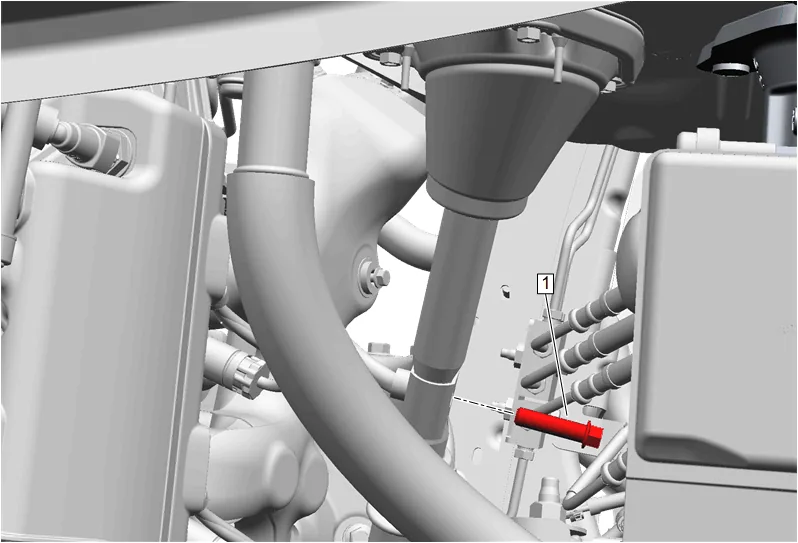
- Mid Intermediate Steering Shaft Bolt (1) » Remove
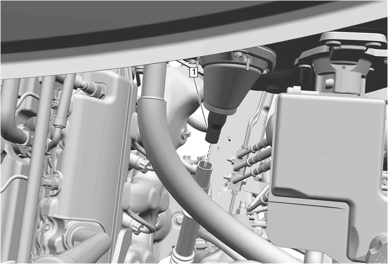
- Upper Intermediate Steering Shaft (1) @ Intermediate Steering Shaft » Separate
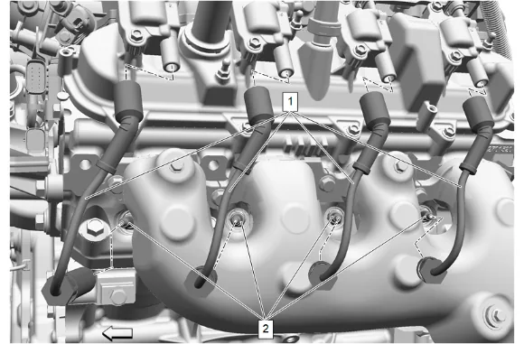
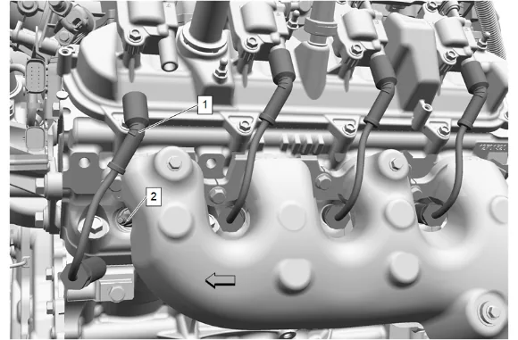
- Twist the 4 spark plug wire boots 1/2 turn and remove the 4 spark plug wires (1) from the 4 gas engine ignition spark plugs (2).
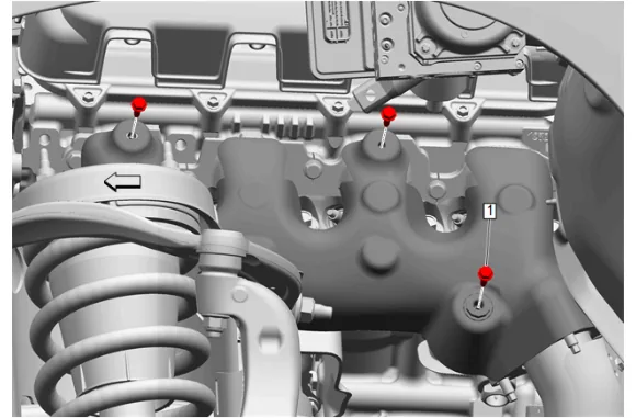
- Exhaust Manifold Heat Shield Bolt - Left Side (1) » Remove [3x]
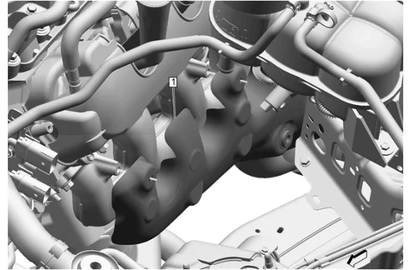
- Exhaust Manifold Heat Shield - Left Side (1) » Remove
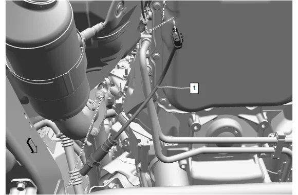
- Disconnect the heated oxygen sensor electrical connector.
- Using a suitable tool, remove the heated oxygen sensor (1).
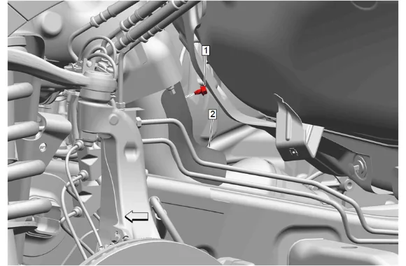
- Exhaust Heat Shield Bolt - Left Side (1) » Remove
- Exhaust Front Pipe Heat Shield - Left Side (2) » Remove
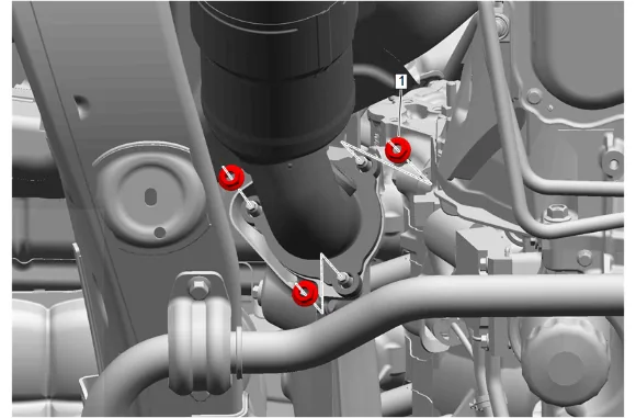
- Exhaust Front Pipe Nut - Left Side (1) » Remove [3x]
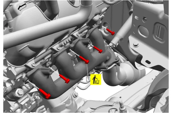
- Exhaust Manifold Bolt - Left Side (1) » Remove and DISCARD [5x]

- Exhaust Manifold - Left Side (1) » Remove
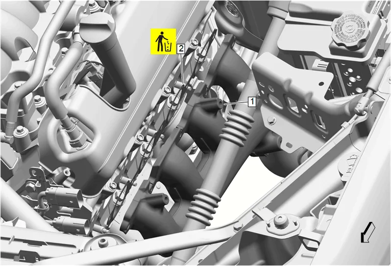
- Exhaust Manifold Gasket - Left Side (2) » Remove and DISCARD
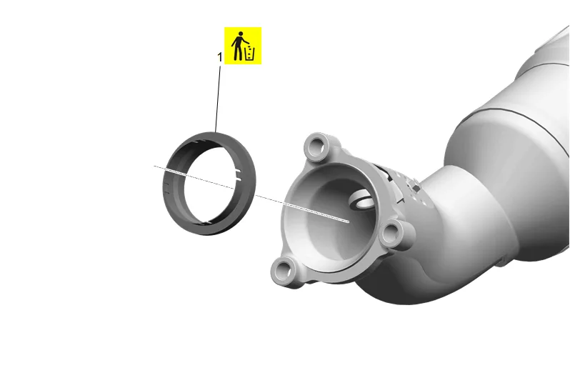
- Exhaust System Seal - Left Side (1) » Remove and DISCARD
- Lower the vehicle.
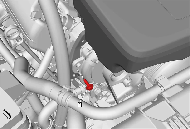
- Air Cleaner Outlet Duct Bracket Bolt (1) » Remove
- Remove engine wiring harness from air cleaner outlet duct bracket.
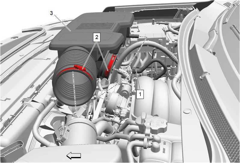
- Positive Crankcase Ventilation Fresh Air Tube (1) » Disconnect — Plastic Collar Quick Connect Fitting Service
- Air Cleaner Outlet Duct Clamp (2) » Loosen [2x]
- Air Cleaner Outlet Duct (3) » Remove
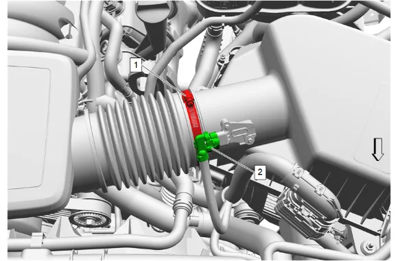
- Disconnect the mass airflow sensor electrical connector (2) and remove all engine wiring harnesses from the air cleaner assembly.
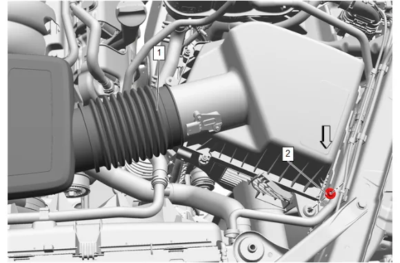
- Air Cleaner Nut (2) » Remove
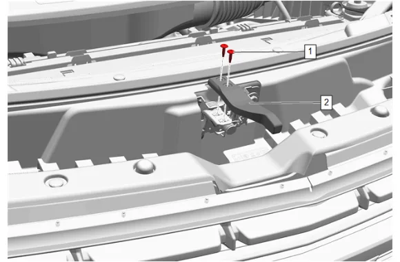
- Hood Latch Actuator Bolt (1) » Remove [2x]
- Hood Secondary Latch Release Handle (2) » Remove
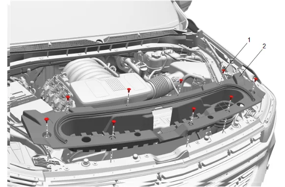
- Intake Air Baffle Retainer (1) » Remove [9x]
- Intake Air Splash Shield (2) » Remove
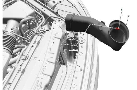
- Intake Air Duct Retainer (1) » Remove
- Intake Air Duct (2) » Reposition
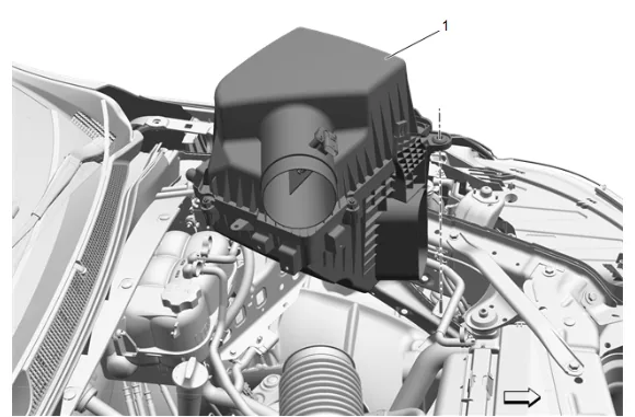
- Air Cleaner Assembly (1) » Remove
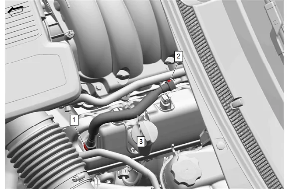
- Positive Crankcase Ventilation Tube Connector (1) @ Positive Crankcase Ventilation Fitting » Disconnect — Plastic Collar Quick Connect Fitting Service
- Positive Crankcase Ventilation Tube Connector (2) @ Intake Manifold » Disconnect — Plastic Collar Quick Connect Fitting Service
- Positive Crankcase Ventilation Foul Air Tube (3) » Remove
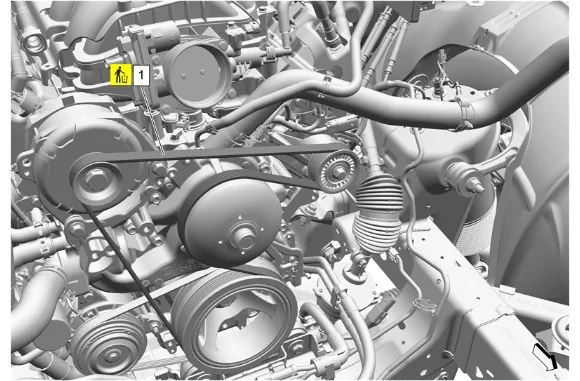
- Using a suitable tool, cut the accessory drive primary belt (1).
- Accessory Drive Primary Belt (1) » Remove and DISCARD
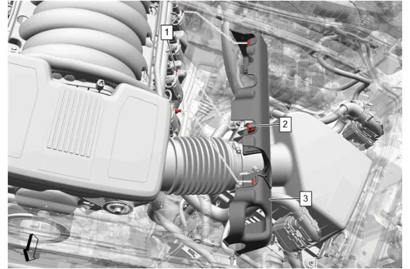
- Grasp the valve rocker arm cover insulator (3) and lift up disengaging the 3 upper intake manifold sight shield grommets (2) from the 3 valve rocker arm cover insulator retainers (1).
- Valve Rocker Arm Cover Insulator (3) » Remove
- Inspect the 3 upper intake manifold sight shield grommets (2) on the valve rocker arm cover insulator and replace as necessary.
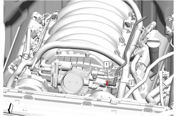
- Evaporative Emission Canister Purge Tube Connector (1) @ Evaporative Emission Canister Purge Solenoid Valve » Disengage — Plastic Collar Quick Connect Fitting Service
- Evaporative Emission Canister Purge Tube (2) @ Evaporative Emission Canister Purge Solenoid Valve » Remove and position aside
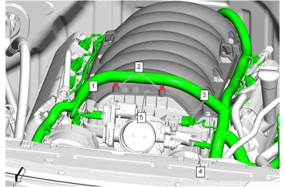
- Engine Wiring Harness Connector (1) @ Throttle Body » Disconnect
- Engine Wiring Harness Retainer (2) @ Intake Manifold Cover » Remove [2x]
- Engine Wiring Harness Connector (3) @ Manifold Absolute Pressure Sensor » Disconnect
- Engine Wiring Harness Connector (4) @ Evaporative Emission Canister Purge Solenoid Valve » Disconnect
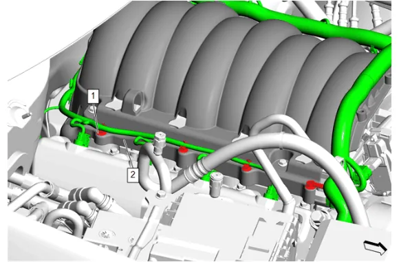
- Engine Wiring Harness Retainer (1) @ Intake Manifold Cover (2) » Remove [4x]
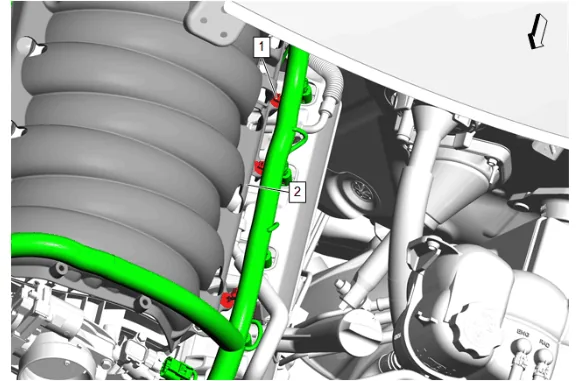
- Engine Wiring Harness Retainer (1) @ Intake Manifold Cover (2) » Remove [3x]
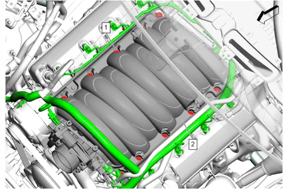
- Loosen the 10 intake manifold bolts (1) until the bolts are no longer threaded into the cylinder heads.
- Move the intake manifold and intake manifold cover (2) forward enough to gain access to the rear engine wiring harness retainers.
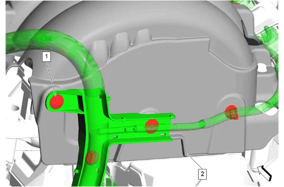
- Engine Wiring Harness Retainer (1) @ Intake Manifold Cover (2) » Remove [4x]
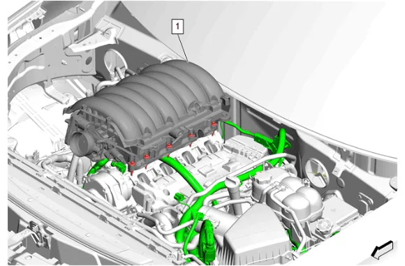
- Remove the intake manifold and intake manifold cover (1) as an assembly.
- Cover the cylinder head passages in order to prevent dirt or debris from entering the passages.
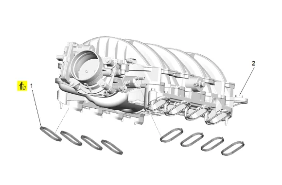
- Intake Manifold Gasket (1) » Remove and DISCARD [8x]
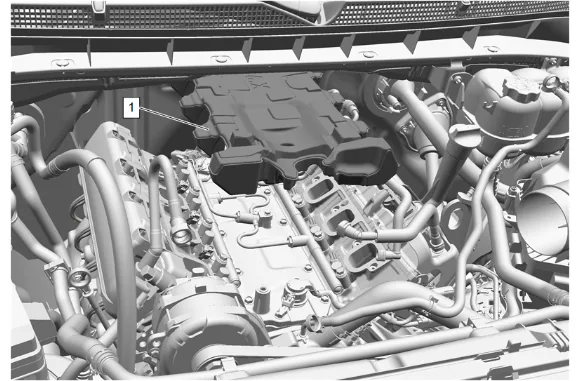
Danger: The noise cancelling foam component MUST be replaced if it has been exposed to engine fluids. Failure to replace the noise cancelling foam component that has been exposed to engine fluids may result in an engine fire resulting in catastrophic engine damage, and possible injury or death. 57. Fuel Pump Insulator (1) » Remove
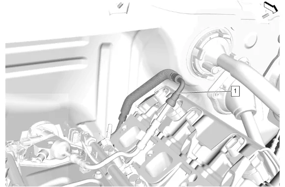
- Fuel Feed Pipe (1) » Disconnect — Metal Collar Quick Connect Fitting Service
- Fuel Feed Pipe (1) » Reposition
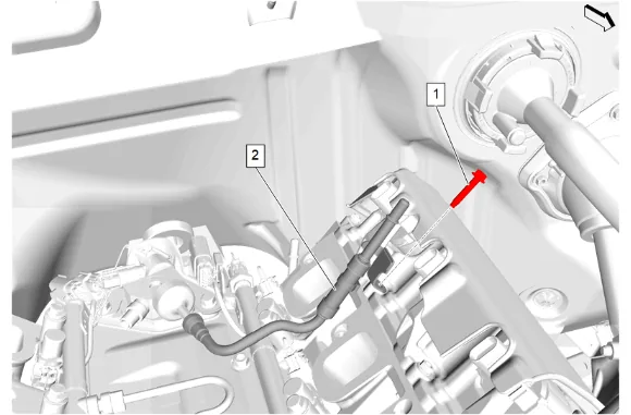
- Fuel Feed Pipe Bolt (1) » Remove
- Fuel Feed Pipe (2) » Disconnect — Metal Collar Quick Connect Fitting Service
- Fuel Feed Pipe (2) » Reposition
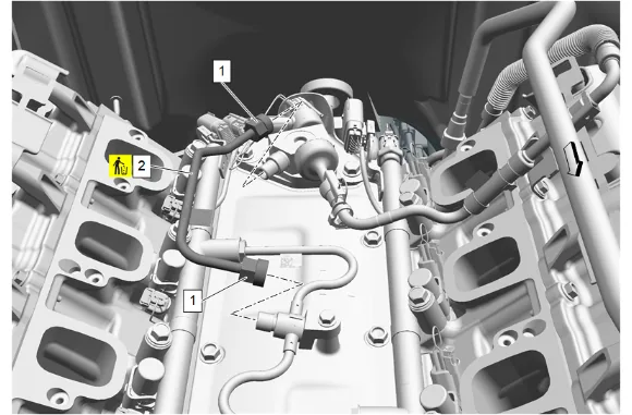
- Fuel Feed Intermediate Pipe Nut (1) @ Fuel Feed Intermediate Pipe (2) » Loosen until disengaged [2x]
- Fuel Feed Intermediate Pipe (2) » Remove and DISCARD
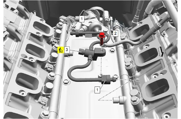
- Fuel Feed Intermediate Pipe Nut (1) » Loosen until disengaged [2x]
- Fuel Feed Pipe Bolt (2) » Remove
- Fuel Feed Intermediate Pipe (3) » Remove and DISCARD
- Disconnect the electrical wiring harness connectors from the fuel rails as needed.
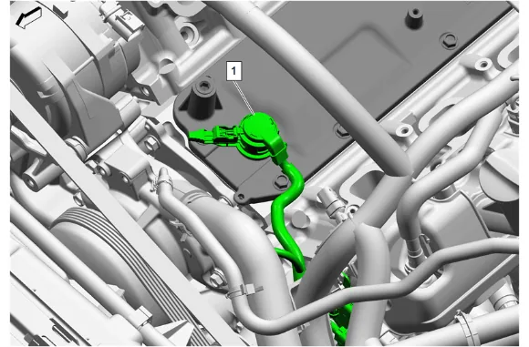
- Valve Rocker Arm Oil Control Valve Extension Harness (1) @ Valve Rocker Arm Oil Control Valve Harness » Disconnect
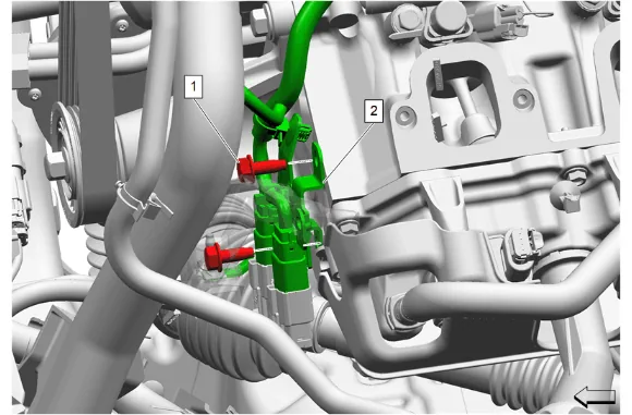
- Engine Wiring Harness Bolt (1) » Remove [2x]
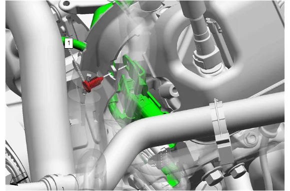
- Wiring Harness Retainer (1) » Remove
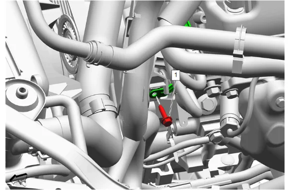
- Engine Wiring Harness Bracket Bolt (1) » Remove
- Engine Wiring Harness » Reposition
- Engine Wiring Harness Connector @ Ignition Coil » Disconnect [4x]
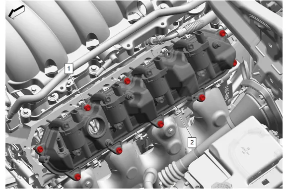
- Valve Rocker Arm Cover Bolt (1) » Loosen until disengaged [9x]
- Valve Rocker Arm Cover - Left Side (2) » Remove
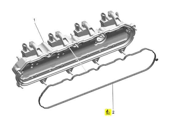
- Valve Rocker Arm Cover Gasket (2) @ Valve Rocker Arm Cover (1) » Remove and DISCARD
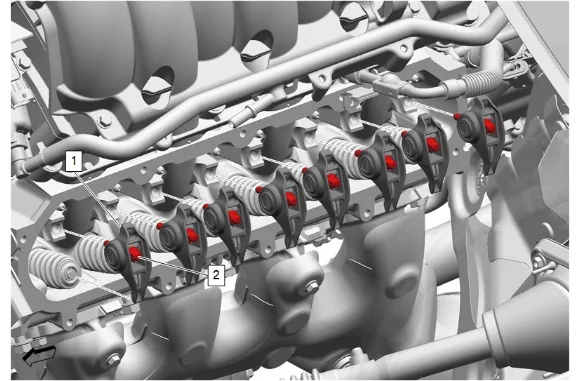
- Valve Rocker Arm Pivot Support Bolt (2) » Loosen until disengaged [8x]
- Valve Rocker Arm (1) » Remove [8x]
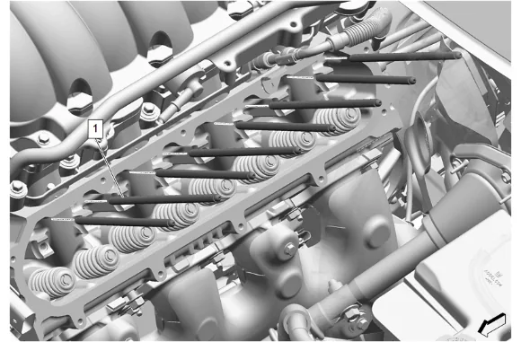
- Valve Push Rod (1) » Remove [8x]
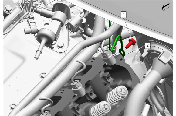
- Engine Wiring Harness Ground Bolt (1) » Remove
- Engine Wiring Harness (2) » Remove
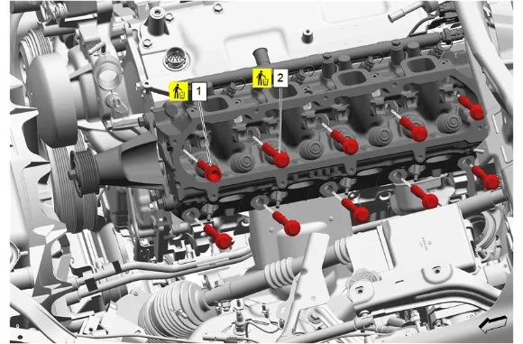
- Cylinder Head Bolt - M12 x 102 (1) » Remove and DISCARD
- Cylinder Head Bolt - M12 x 134 (2) » Remove and DISCARD [9x]
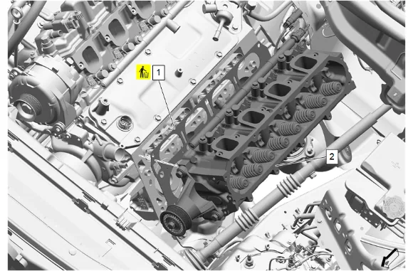
- Cylinder Head (2) » Remove
- Cylinder Head Gasket (1) » Remove and DISCARD
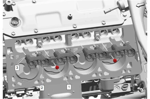
- Valve Lifter Guide Bolt (1) » Loosen until disengaged
- Remove the valve lifter guide (2) and the valve lifters (3) as an assembly.
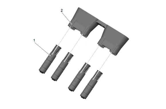
- Valve Lifter (1) @ Valve Lifter Guide (2) » Remove
- Using the appropriate tool, clean and prepare the applicable sealing surface. Cleaning and Inspection Procedure - Conditional
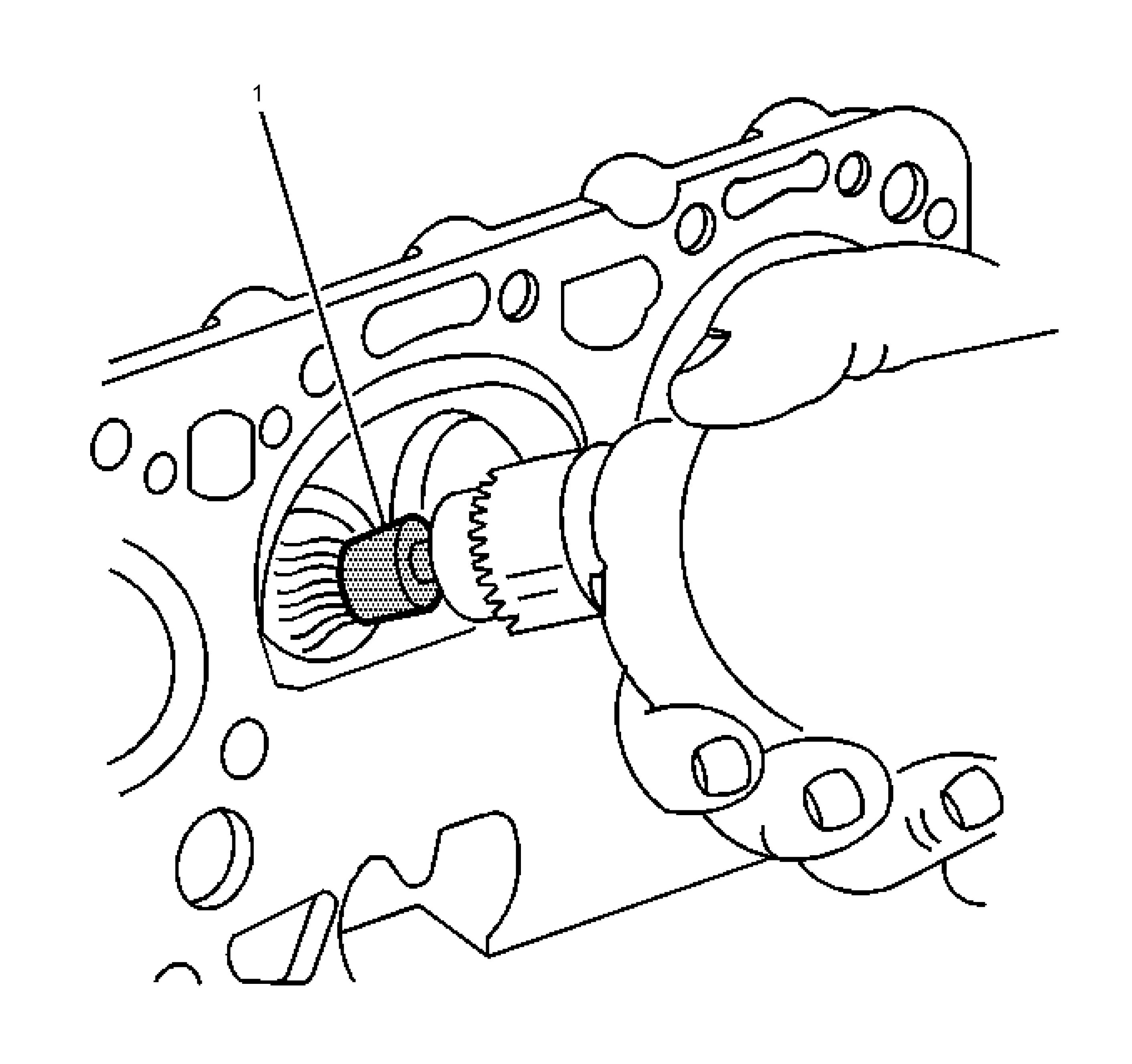
- Clean the following components: 1.1. Use the J-8089 Carbon Removal Brush (1) in order to remove the carbon from the combustion chambers. 1.2. Gasket surfaces 1.3. Valve stems and heads on a buffing wheel 1.4. Bolt hole threads 1.5. Remove all dirt, debris, or threadlocking material from the bolt holes.
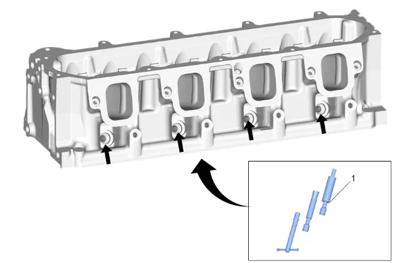
- Inspect the fuel rail injector bores and clean with EN-47909 Injector Bore and Sleeve Cleaning Kit (1), if required.
- Inspect the cylinder head for the following conditions: 3.1. Cracks in the exhaust ports and combustion chambers 3.2. External cracks in the water chambers 3.3. Gasket surfaces for excessive scratches or gouging 3.4. Bolt hole threads for debris or damaged threads Thread Repair Thread Repair Specifications
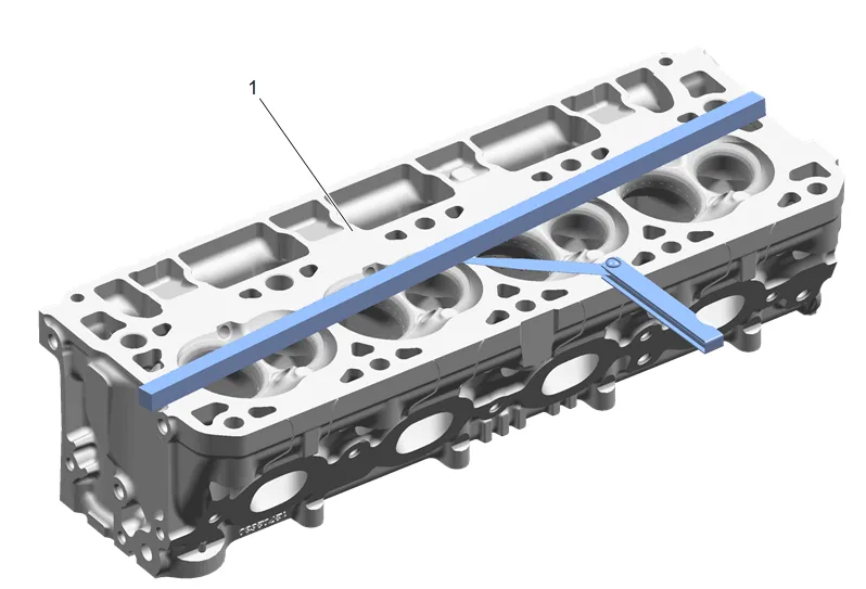
- Inspect the cylinder head for warpage. Engine Mechanical Specifications
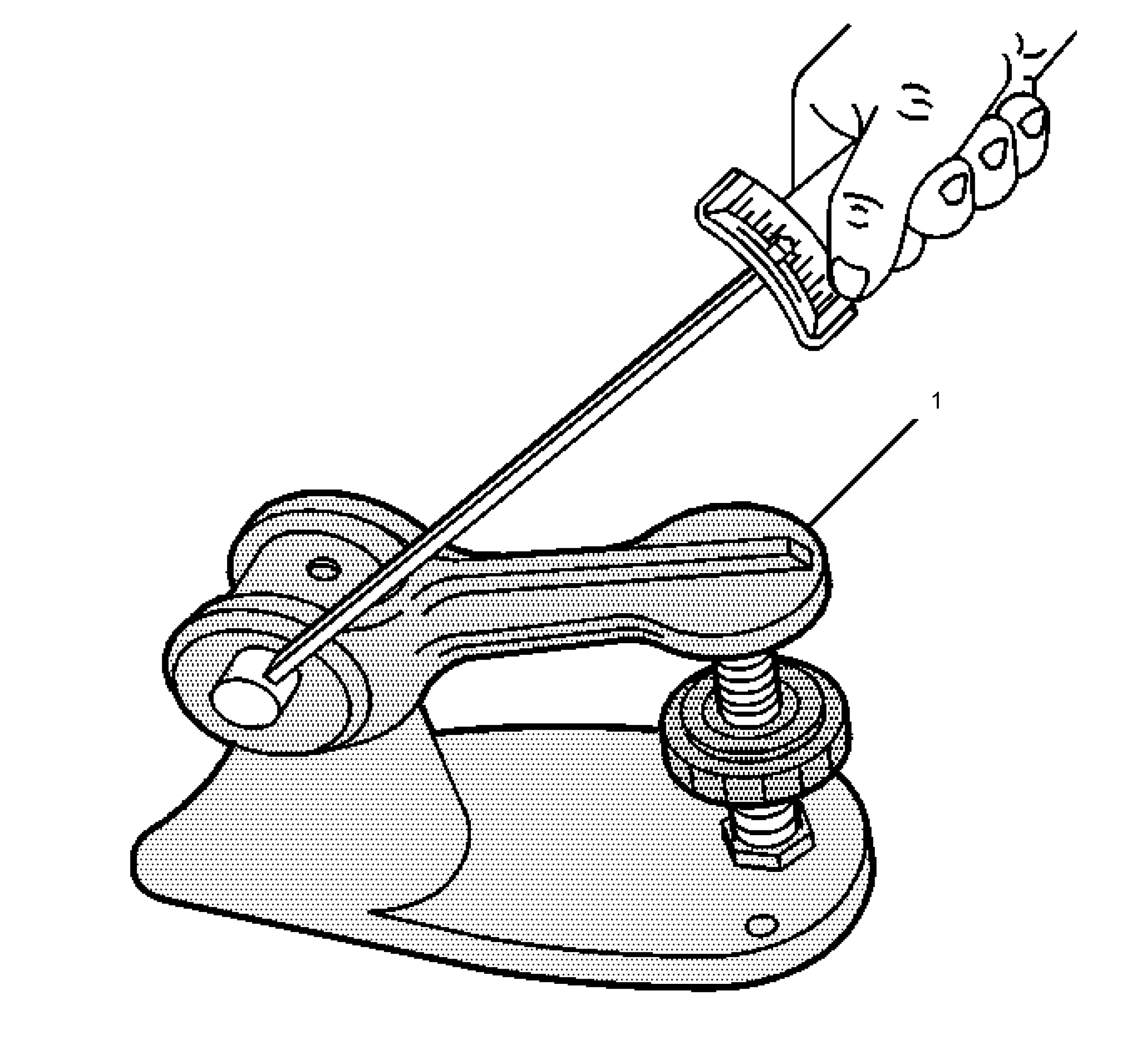
- Using the J-9666 Valve Spring Tester (1), measure the valve spring tension. Engine Mechanical Specifications.
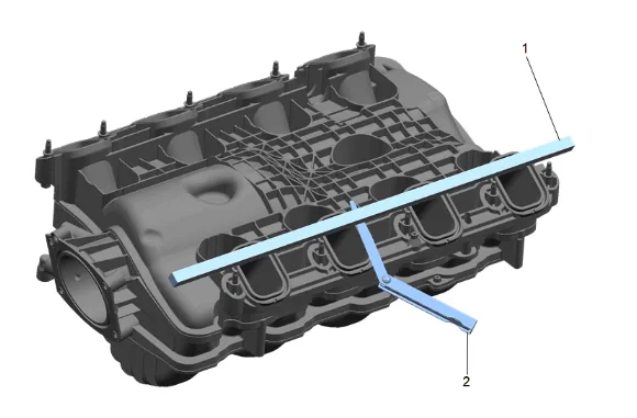
- Clean all sealing surfaces.
- Dry the intake manifold with compressed air.
- Inspect the intake manifold cylinder head deck for warpage.
- Place a straight edge (1) across the intake manifold cylinder head deck surface.
- Inspect the intake manifold for the following conditions: 10.1. Inspect for loose threaded inserts or studs. 10.2. Inspect for damaged or broken vacuum fitting. 10.3. Inspect the intake manifold assembly for cracks or other damage. 10.4. Inspect for damaged intake manifold gasket sealing surfaces.
- Position the straight edge (1) across a minimum of two runner port openings and check for warpage using a feeler gage. Engine Mechanical Specifications
- Inspect the ventilation system passages for restrictions.
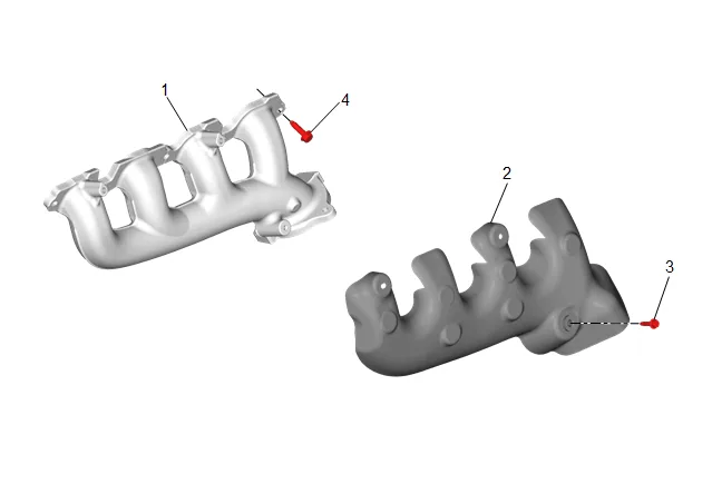
- Clean the exhaust manifold (1) and heat shield (2) in solvent.
- Dry the exhaust manifold (1) with compressed air.
- Inspect the exhaust manifold (1) to the cylinder head exhaust manifold gasket surface for excessive scratches or gouging.
- Inspect for a loose, damaged, or cracked heat shield (2).
- Inspect the heat shield bolts (3) for damaged threads.
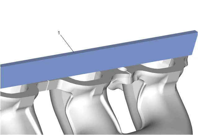
- Use a straight edge (1) and a feeler gauge and measure the exhaust manifold cylinder head deck for warpage. An exhaust manifold cylinder head deck with warpage in excess of 0.25 mm (0.01 in) within the 2 front or 2 rear runners or 0.5 mm (0.02 in) overall, may cause an exhaust leak. Exhaust manifolds not within specifications MUST be replaced.
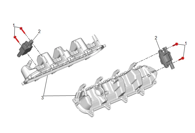
- Remove the 8 ignition coil bolts (1) and 4 ignition coils (2) before cleaning the valve rocker arm cover (3) in solvent. Do NOT submerge the 4 ignition coils (2) in solvent.
- Inspect the valve rocker arm cover (3) for the following conditions: 20.1. Scoring or damage to the gasket surfaces 20.2. Ventilation system passages for restrictions 20.3. Threaded bolt holes for damage or debris
- Install the 4 ignition coils (2).
- Install and tighten the 8 ignition coil bolts (1). Fastener Specifications
- Clean the components in cleaning solvent.
- Dry the components with compressed air.
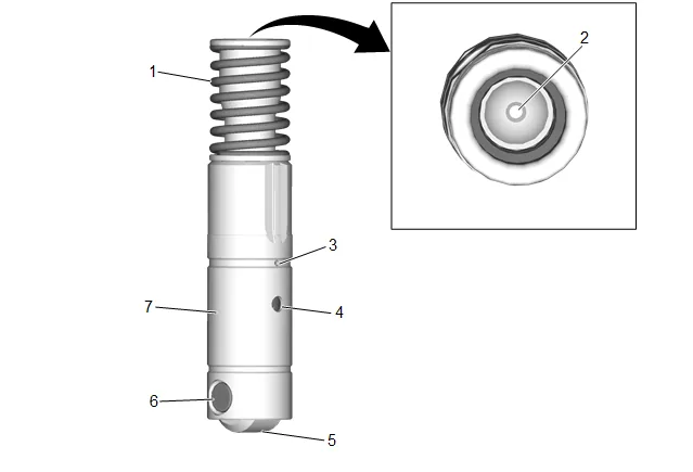
- Inspect the valve lifters for the following conditions: 25.1. Broken or collapsed spring (1) 25.2. Worn pushrod socket (2) 25.3. Plugged lubrication hole (3) 25.4. Plugged lifter oil switching hole (4) 25.5. Flat spots on the roller (5) 25.6. Worn or damaged roller bearing (6) The roller should rotate freely with no binding or roughness. 25.7. Scuffed or worn sides (7)
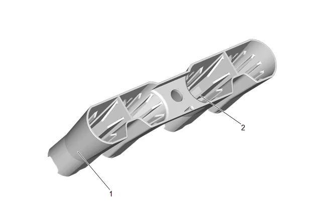
- Inspect the valve lifter guides for the following conditions:
- Cracks or damage (1)
- Excessive wear in the lifter mounting bores (2)
- Mark, sort, or organize the components for assembly.
- Clean the components with cleaning solvent.
- Dry the components with compressed air.
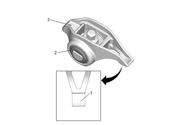
- Inspect the valve rocker arms bearings (2) for binding or roughness.
- Inspect the valve rocker arm pushrod sockets (3) and valve stem mating surfaces (1). These surfaces should be smooth with no scoring or exceptional wear.
- Inspect the pushrods for worn or scored ends. These surfaces should be smooth with no scoring or exceptional wear.
- Inspect the pushrods for bends. Roll the pushrod on a flat surface to determine if the pushrod is bent.
- Inspect the pushrod oil passages for restrictions.
- Inspect the rocker arm pivot supports for cracks, wear, or other damage.
- Inspection the spark plug wire for the following conditions: 38.1. Correct routing of the spark plug wires. Incorrect routing may cause cross-firing. 38.2. Inspect for any signs of cracks or splits in the wires.
- Inspect each boot for the following conditions: 39.1. Tearing 39.2. Piercing 39.3. Arcing 39.4. Carbon tracking 39.5. Corroded terminals
- If corrosion, carbon tracking or arcing are indicated on a spark plug wire boot or on a terminal, replace the wire and the component connected to the wire. Installation Procedure
- Lubricate the valve lifters and valve lifter guides with clean engine oil. Adhesives, Fluids, Lubricants, and Sealers
- Install the raised surface of the valve lifter (1) into the notched area of the valve lifter guide (2).
- Install the valve lifter guide (2) and the valve lifters (3) as an assembly.
- Valve Lifter Guide Bolt (1) » Install and tighten — Fastener Specifications
- Cylinder Head Gasket (1) » Install NEW
- Cylinder Head (2) » Install
-
Cylinder Head Bolt - M12 x 134 (2) » Install NEW and hand tighten [9x]
-
Cylinder Head Bolt - M12 x 102 (1) » Install NEW and hand tighten
-
Cylinder Head Bolt (1, 2) » Tighten in sequence [10x] — Fastener Specifications
-
Engine Wiring Harness (2) » Install
-
Engine Wiring Harness Ground Bolt (1) » Install and tighten — Ground Repair
-
Lubricate the flange of the 8 valve rocker arm bolts with clean engine oil. Adhesives, Fluids, Lubricants, and Sealers
-
Lubricate the 8 valve rocker arms and push rods with clean engine oil. Adhesives, Fluids, Lubricants, and Sealers
- Valve Push Rod (1) » Install [8x]
-
Valve Rocker Arm (1) » Install [8x]
-
Valve Rocker Arm Pivot Support Bolt (2) » Hand tighten [8x]
-
Valve Rocker Arm Pivot Support Bolt (2) » Tighten [8x] — Fastener Specifications
-
Valve Rocker Arm Cover Gasket (2) @ Valve Rocker Arm Cover (1) » Install NEW
-
Valve Rocker Arm Cover - Left Side (2) » Install
-
Valve Rocker Arm Cover Bolt (1) » Hand tighten [9x]
-
Valve Rocker Arm Cover Bolt (1) » Tighten in sequence [9x] — Fastener Specifications
-
Fuel Feed Pipe (2) » Reposition
-
Fuel Feed Pipe Bolt (1) @ Fuel Feed Pipe (2) » Install and tighten — Fastener Specifications
-
Fuel Feed Pipe (1) » Reposition
-
Fuel Feed Pipe (1) » Connect — Metal Collar Quick Connect Fitting Service
-
Engine Wiring Harness Connector @ Ignition Coil » Connect [4x]
-
Engine Wiring Harness » Reposition
-
Engine Wiring Harness Bracket Bolt (1) » Install and hand tighten
-
Wiring Harness Retainer (1) » Install
-
Engine Wiring Harness Bolt (1) » Install and hand tighten [2x]
-
Engine Wiring Harness Bolt (1) » Tighten [2x] — Fastener Specifications
-
Engine Wiring Harness Bracket Bolt (1) » Tighten — Fastener Specifications
-
Valve Rocker Arm Oil Control Valve Extension Harness (1) @ Valve Rocker Arm Oil Control Valve Harness » Connect
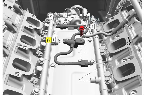
- Fuel Feed Intermediate Pipe (1) » Install NEW 34.1. Slide the 2 fuel feed intermediate pipe nuts (3) back along fuel feed intermediate pipe (1) to reveal the 2 formed ends (2) of the fuel feed intermediate pipe (1). 34.2. Carefully install the 2 formed ends (2) of the fuel feed intermediate pipe (1) into the sockets of the left and right fuel injection fuel rail. Take care not to hit the 2 formed ends (2) of the fuel feed intermediate pipe (1) on the threaded sockets on the fuel injection fuel rails. 34.3. Hold the fuel feed intermediate pipe (1) firmly in place and hand tighten the 2 fuel feed intermediate pipe nuts (3).
- Fuel Feed Pipe Bolt (4) » Tighten — Fastener Specifications
- Fuel Feed Intermediate Pipe Nut (3) » Tighten [2x] — Fastener Specifications
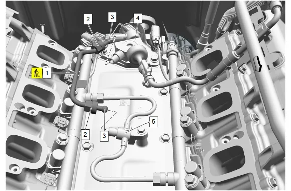
- Fuel Feed Intermediate Pipe (1) » Install NEW 37.1. Slide the 2 fuel feed intermediate pipe nuts (2) back along fuel feed intermediate pipe (1) to reveal the 2 formed ends (3) of the fuel feed intermediate pipe (1). 37.2. Carefully install the 2 formed ends (3) of the fuel feed intermediate pipe (1) into the sockets of the fuel pump (4) and the fuel feed intermediate pipe (5). Take care not to hit the 2 formed ends (3) of the fuel feed intermediate pipe (1) on the threaded sockets of the fuel pump (4) and fuel feed intermediate pipe (5). 37.3. Hold the fuel feed intermediate pipe (1) firmly in place and hand tighten the 2 fuel feed intermediate pipe nuts (2).
- Fuel Feed Intermediate Pipe Nut (2) » Tighten [2x] — Fastener Specifications
- Connect the electrical wiring harness connectors to the fuel rails as needed.
Danger: The noise cancelling foam component MUST be replaced if it has been exposed to engine fluids. Failure to replace the noise cancelling foam component that has been exposed to engine fluids may result in an engine fire resulting in catastrophic engine damage, and possible injury or death. 40. Fuel Pump Insulator (1) » Install 41. Remove the covers from the cylinder head passages.
-
Intake Manifold Gasket (1) » Install NEW [8x]
-
If NEW threaded components are being installed, loosen the adhesive using a metal pick or similar tool before proceeding. If threaded components are reused, prepare the threaded components using the following steps: 43.1. Remove any loose cured adhesive from the external threads of the components using a lint free cloth. 43.2. Thread the cleaned components into the internal mating threads and remove to loosen trapped cured adhesive. 43.3. Apply thread locking adhesive to the external threads of the components. Adhesives, Fluids, Lubricants, and Sealers 43.4. Ensure there are no gaps in the thread locking adhesive once applied to the component.
-
Position the intake manifold and Intake manifold cover (1) to install harness retainers.
-
Engine Wiring Harness Retainer (1) @ Intake Manifold Cover (2) » Install [4x]
-
Move the intake manifold and intake manifold cover (2) into place.
-
Intake Manifold Bolt (1) » Hand tighten [10x]
-
Intake Manifold Bolt (1) » Tighten in sequence [10x] — Fastener Specifications
-
Engine Wiring Harness Retainer (1) @ Intake Manifold Cover (2) » Install [3x]
-
Engine Wiring Harness Retainer (1) @ Intake Manifold Cover (2) » Install [4x]
-
Engine Wiring Harness Connector (4) @ Evaporative Emission Canister Purge Solenoid Valve » Connect
-
Engine Wiring Harness Connector (3) @ Manifold Absolute Pressure Sensor » Connect
-
Engine Wiring Harness Retainer (2) @ Intake Manifold Cover » Install [2x]
-
Engine Wiring Harness Connector (1) @ Throttle Body » Connect
-
Evaporative Emission Canister Purge Tube (2) @ Evaporative Emission Canister Purge Solenoid Valve » Install
-
Evaporative Emission Canister Purge Tube Connector (1) @ Evaporative Emission Canister Purge Solenoid Valve » Engage — Plastic Collar Quick Connect Fitting Service
-
Valve Rocker Arm Cover Insulator (3) » Install
-
Install the 3 upper intake manifold sight shield grommets (2) to the 3 valve rocker arm cover insulator retainers (1).
-
Positive Crankcase Ventilation Foul Air Tube (3) » Install
-
Positive Crankcase Ventilation Tube Connector (2) @ Intake Manifold » Connect — Plastic Collar Quick Connect Fitting Service
-
Positive Crankcase Ventilation Tube Connector (1) @ Positive Crankcase Ventilation Fitting » Connect — Plastic Collar Quick Connect Fitting Service
-
Raise the vehicle.
-
Exhaust System Seal - Left Side (1) » Install NEW
-
Exhaust Manifold Gasket - Left Side (2) » Install NEW
-
Exhaust Manifold - Left Side (1) » Install
-
If NEW threaded components are being installed, loosen the adhesive using a metal pick or similar tool before proceeding. If threaded components are reused, prepare the threaded components using the following steps: 66.1. Remove any loose cured adhesive from the external threads of the components using a lint free cloth. 66.2. Thread the cleaned components into the internal mating threads and remove to loosen trapped cured adhesive. 66.3. Apply thread locking adhesive to the external threads of the components. Adhesives, Fluids, Lubricants, and Sealers 66.4. Ensure there are no gaps in the thread locking adhesive once applied to the component.
-
Exhaust Manifold Bolt - Left Side (1) » Install NEW and hand tighten [5x]
-
Exhaust Manifold Bolt - Left Side (1) » Tighten [5x] — Fastener Specifications
-
Exhaust Manifold Heat Shield - Left Side (1) » Install
-
Through the wheel opening, install and tighten the 3 left side exhaust manifold heat shield bolts (1). Fastener Specifications
-
Inspect the inside of the spark plug rubber boots for a thin, even coat of grease. If there is no grease present or additional grease is necessary, apply a thin coating of dielectric grease evenly to the inside of the spark plug rubber boots up to a depth of 15 mm (0.6 in) from the end of the boot. Adhesives, Fluids, Lubricants, and Sealers
-
Push the 4 boots of the spark plug wires (1) onto the 4 gas engine ignition spark plugs (2) until 2 audible clicks are heard.
-
Upper Intermediate Steering Shaft (1) @ Intermediate Steering Shaft » Install
-
If a NEW threaded component is being installed, loosen the adhesive using a metal pick or similar tool before proceeding. If threaded component is reused, prepare the threaded component using the following steps: 74.1. Remove any loose cured adhesive from the external threads of the component using a lint free cloth. 74.2. Thread the cleaned component into the internal mating threads and remove to loosen trapped cured adhesive. 74.3. Apply thread locking adhesive to the external threads of the component. Adhesives, Fluids, Lubricants, and Sealers 74.4. Ensure there are no gaps in the thread locking adhesive once applied to the component.
-
Mid Intermediate Steering Shaft Bolt (1) » Install and tighten — Fastener Specifications
-
Exhaust Front Pipe Nut - Left Side (1) » Install and hand tighten [3x]
-
Exhaust Front Pipe Nut - Left Side (1) » Tighten [3x] — Fastener Specifications
-
Exhaust Front Pipe Heat Shield (2) » Install
-
Exhaust Heat Shield Bolt (1) » Install and tighten — Fastener Specifications
- Using a suitable tool, install and tighten the heated oxygen sensor (1). Fastener Specifications
- Connect the heated oxygen sensor electrical connector.
- Front Wheelhouse Liner - Left Side » Install — Front Wheelhouse Liner Replacement
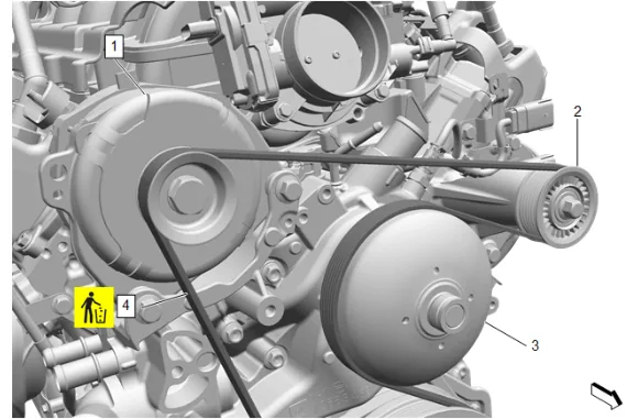
- Position the accessory drive primary belt (4) on the belt idler pulley (2), fan and water pump pulley (3) and generator (1).
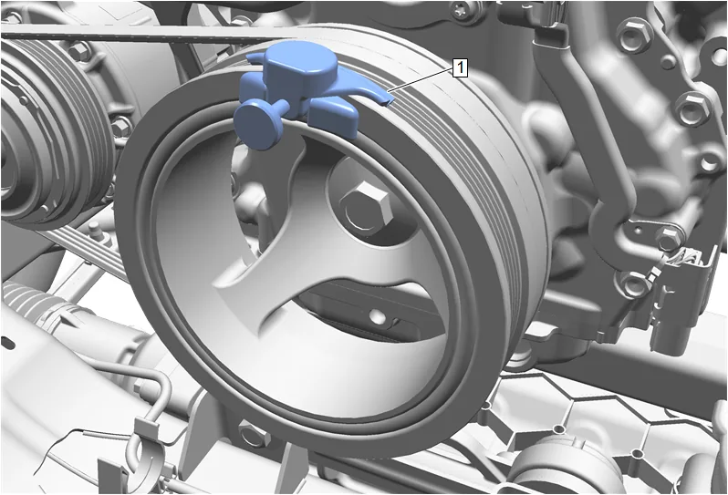
- Install the EN-51767-2 Stretchy Belt Installer (1) onto the crankshaft balancer.
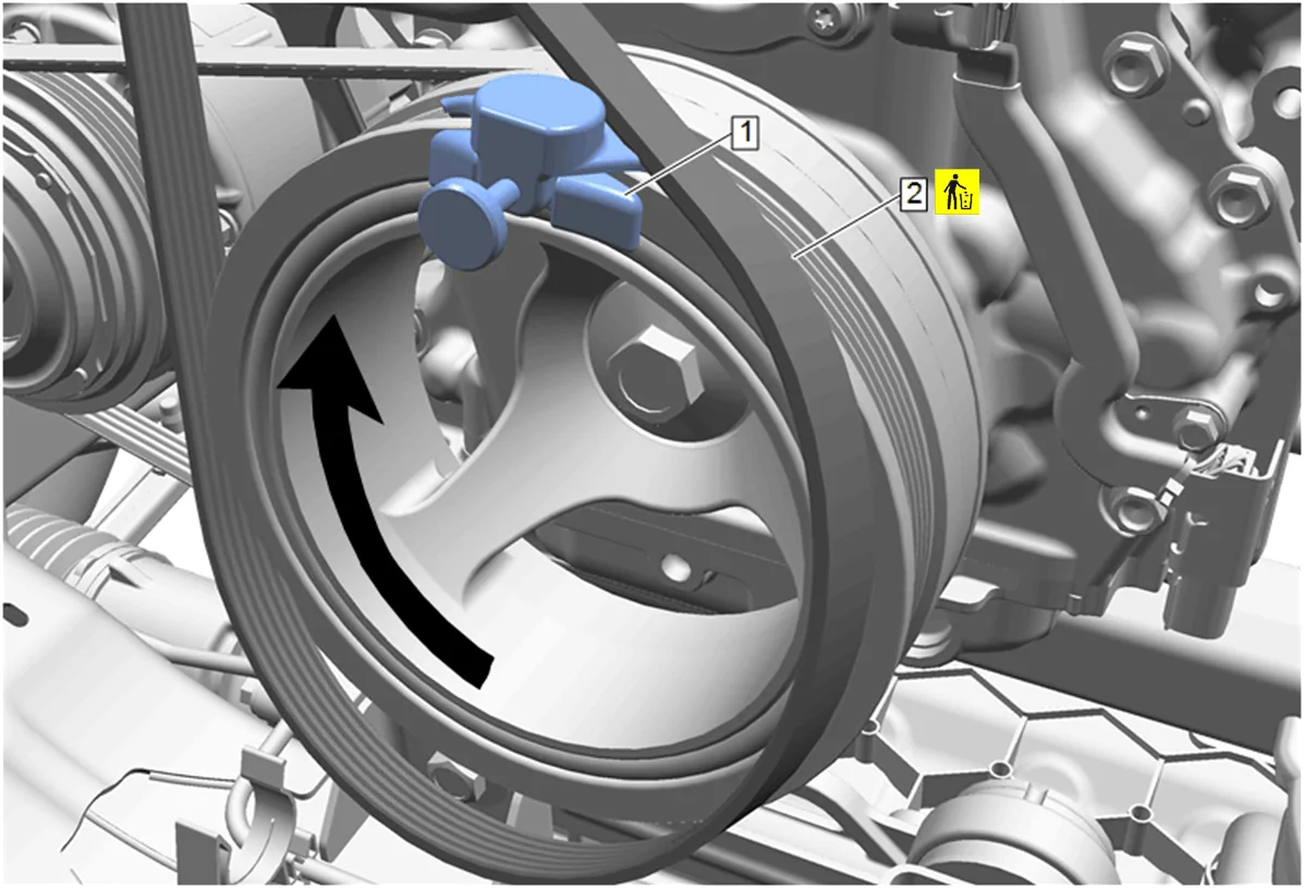
- Position the accessory drive primary belt (2) on the crankshaft balancer.
- Slowly rotate the crankshaft balancer in a clockwise direction until the accessory drive primary belt (2) fully seats on the crankshaft balancer.
- Remove the EN-51767-2 Stretchy Belt Installer (1) from the crankshaft balancer.
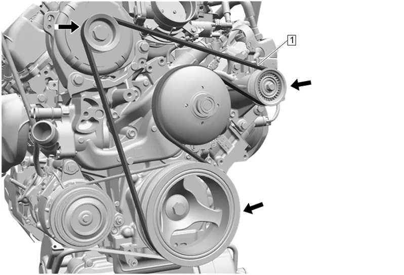
- Inspect the accessory drive primary belt (1) for proper installation and alignment.
-
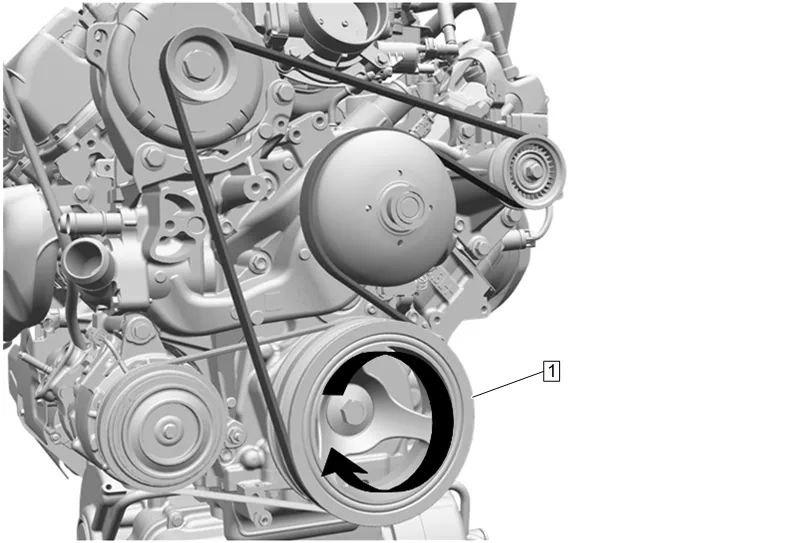
Rotate the crankshaft balancer (1) an additional 360 degrees to ensure proper accessory drive primary belt installation.
-
Air Cleaner Assembly (1) » Install
-
Intake Air Duct (2) » Install
-
Intake Air Duct Retainer (1) » Install
-
Intake Air Splash Shield (2) » Install
-
Intake Air Baffle Retainer (1) » Install [9x]
-
Hood Secondary Latch Release Handle (2) » Install
-
Hood Latch Actuator Bolt (1) » Install and tighten [2x] — Fastener Specifications
-
Air Cleaner Nut (2) » Install and tighten — Fastener Specifications
-
Air Cleaner Outlet Duct (1) » Install
-
Connect the mass airflow sensor electrical connector (2) and engage all engine wiring harnesses to the air cleaner assembly.
-
Air Cleaner Outlet Duct (3) » Install
-
Air Cleaner Outlet Duct Clamp (2) » Tighten [2x] — Fastener Specifications
-
Positive Crankcase Ventilation Fresh Air Tube (1) » Connect — Plastic Collar Quick Connect Fitting Service
-
Install the engine wiring harness to the air cleaner outlet duct bracket.
-
Air Cleaner Outlet Duct Bracket Bolt (1) » Install and tighten — Fastener Specifications
-
Engine Oil and Oil Filter » Install NEW — Engine Oil and Oil Filter Replacement
-
Plenum Front Panel Outer Reinforcement (1) » Install — Plenum Front Panel Outer Reinforcement Removal and Installation
-
Fill the cooling system to the proper level. Cooling System Draining and Filling
-
Start the engine and check for leaks.