Brake Master Cylinder Replacement - With Power Brake Booster and Electronic Brake Control Module
Brake Master Cylinder Replacement - With Power Brake Booster and Electronic Brake Control Module
- Prepare the brake system control module for removal. Control Module References
- Disconnect the battery negative cable. Battery Negative Cable Disconnection and Connection
- Thoroughly clean the brake master cylinder reservoir and the brake master cylinder body to remove any dirt and debris.
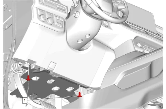
- Instrument Panel Lower Insulator Retainer (1) » Remove [2x]
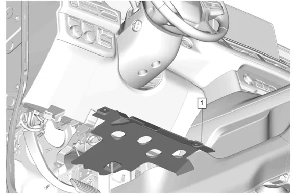
- Instrument Panel Lower Trim Panel Insulator (1) » Remove
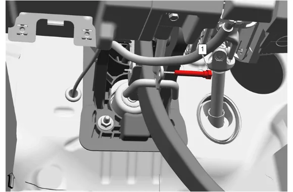
- Brake Pedal Push Rod Bolt (1) » Remove
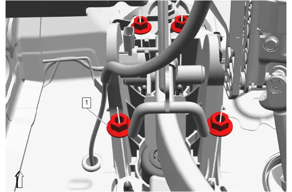
- Brake Pedal Nut (1) » Remove [4x]
- Raise and support the vehicle. Lifting and Jacking the Vehicle
- Remove the left front tire and wheel assembly. Tire and Wheel Removal and Installation
- Front Wheelhouse Liner - Left Side » Remove Front Wheelhouse Liner Replacement
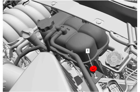
- Radiator Surge Tank Bolt (1) » Remove
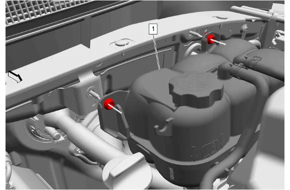
- Without disconnecting the hoses, remove the radiator surge tank and position aside. (1)
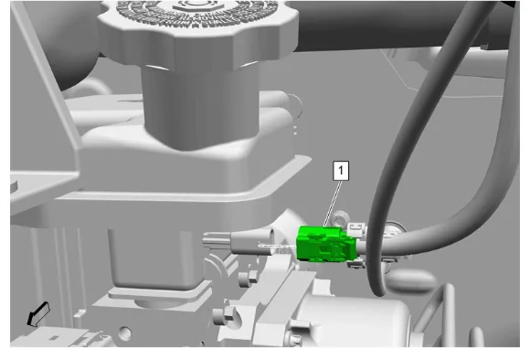
- Electrical Connector (1) @ Brake Fluid Level Indicator Switch » Disconnect
- Place a drain pan under the vehicle.
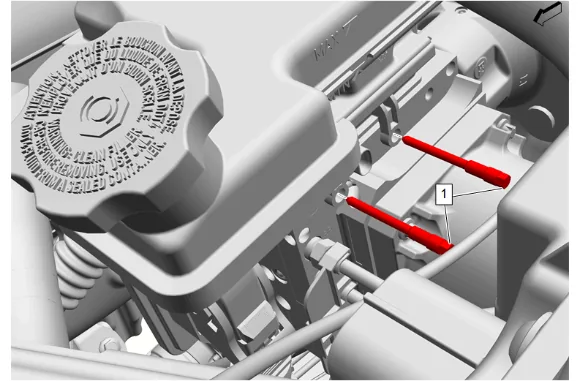
- Brake Master Cylinder Bolt (1) » Remove [2x]
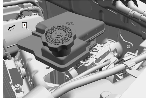
- Brake Master Cylinder Reservoir (1) » Remove
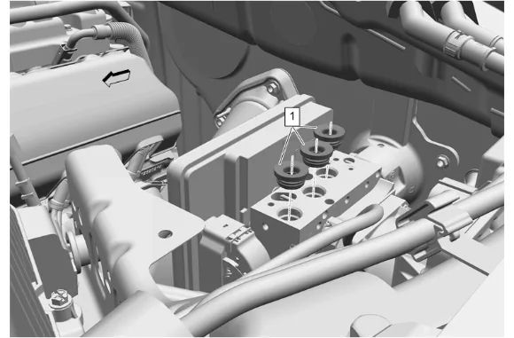
- Brake Master Cylinder Reservoir Seal (1) » Remove and DISCARD [3x]
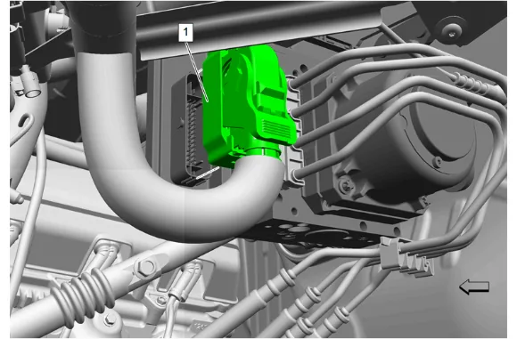
- Electrical Connector (1) @ Brake System Control Module » Disconnect
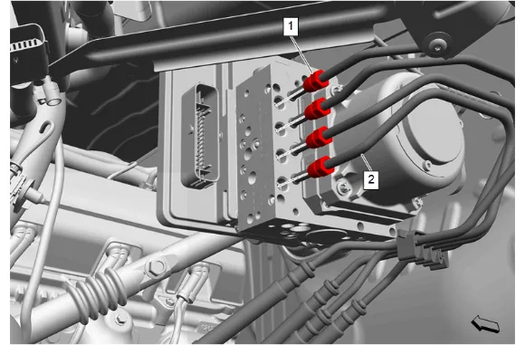
- Label the brake pipes to ensure they are re-installed in the correct ports of the brake master cylinder.
- Front and Rear Brake Pipe Nut (1) » Remove [4x]
- Front and Rear Brake Pipe (2) @ Brake Master Cylinder » Remove
- Cap the front and rear brake pipe inlets to avoid fluid loss and contamination.
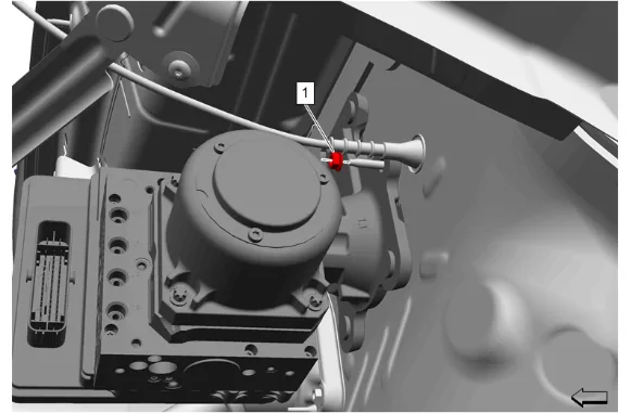
- Brake Master Cylinder Adapter Nut (1) » Remove
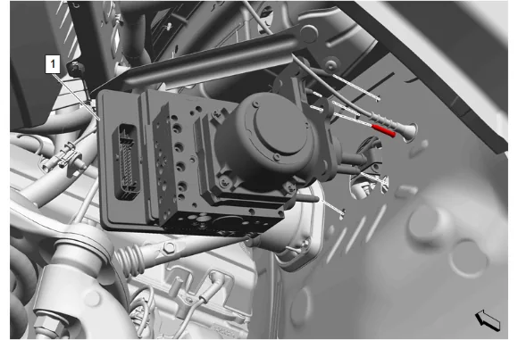
- Maneuver the brake master cylinder (1) out of the vehicle through the wheel well.
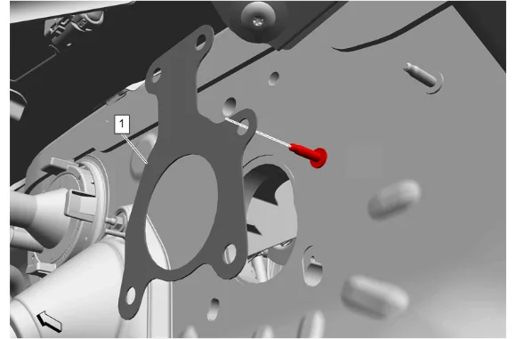
-
Brake Master Cylinder Gasket (1) » Remove
-
Clean any brake fluid from the underbody area and remove the drain pan from under the vehicle. Installation Procedure
-
Brake Master Cylinder Gasket (1) » Install
- Brake Master Cylinder (1) » Install
-
Brake Master Cylinder Adapter Nut (1) » Install and tighten — Fastener Specifications
-
Remove the caps from the front and rear brake pipe inlets.
-
Reinstall the front and rear brake pipes (2) as they were labeled during removal.
-
Front and Rear Brake Pipe Nut (1) » Install and tighten [4x] — Fastener Specifications
-
Electrical Connector @ Brake System Control Module (1) » Connect
-
Lubricate the brake master cylinder reservoir seals (1) with GM approved brake fluid from a clean, sealed brake fluid container. Adhesives, Fluids, Lubricants, and Sealers
-
Brake Master Cylinder Reservoir Seal (1) » Install NEW [3x]
-
Brake Master Cylinder Reservoir (1) » Install
-
Brake Master Cylinder Bolt (1) » Install and tighten [2x] — Fastener Specifications
-
Electrical Connector (1) @ Brake Fluid Level Indicator Switch » Connect
-
Radiator Surge Tank (1) » Install
-
Radiator Surge Tank Bolt (1) » Install and tighten — Fastener Specifications
-
Front Wheelhouse Liner - Left Side » Install Front Wheelhouse Liner Replacement
-
Install the left front tire and wheel assembly. Tire and Wheel Removal and Installation
-
Brake Pedal Nut (1) » Install and tighten [4x] — Fastener Specifications
-
If a NEW threaded component is being installed, loosen the adhesive using a metal pick or similar tool before proceeding. If threaded component is reused, prepare the threaded component using the following steps: 18.1. Remove any loose cured adhesive from the external threads of the component using a lint free cloth. 18.2. Thread the cleaned component into the internal mating threads and remove to loosen trapped cured adhesive. 18.3. Apply thread locking adhesive to the external threads of the component. Adhesives, Fluids, Lubricants, and Sealers 18.4. Ensure there are no gaps in the thread locking adhesive once applied to the component.
-
Brake Pedal Push Rod Bolt (1) » Install and tighten — Fastener Specifications
-
Instrument Panel Lower Trim Panel Insulator (1) » Install
-
Instrument Panel Lower Insulator Retainer (1) » Install [2x]
-
Connect the battery negative cable. Battery Negative Cable Disconnection and Connection
-
Reprogram the brake system control module. Control Module References
-
Bleed the brake system. Hydraulic Brake System Bleeding
-
Fill the brake master cylinder reservoir to the maximum-full level with GM approved brake fluid from a clean, sealed brake fluid container. Brake Master Cylinder Reservoir Filling
-
Check for brake system leaks.