Front Shock Absorber and Spring Removal and Installation - Left Side (ZW7, Z56)
Front Shock Absorber and Spring Removal and Installation - Left Side (ZW7, Z56) Special Tools CH-42188–B Ball Joint Separator Equivalent regional tools: Special Tools Removal Procedure
- Remove the front tire and wheel assembly. Tire and Wheel Removal and Installation
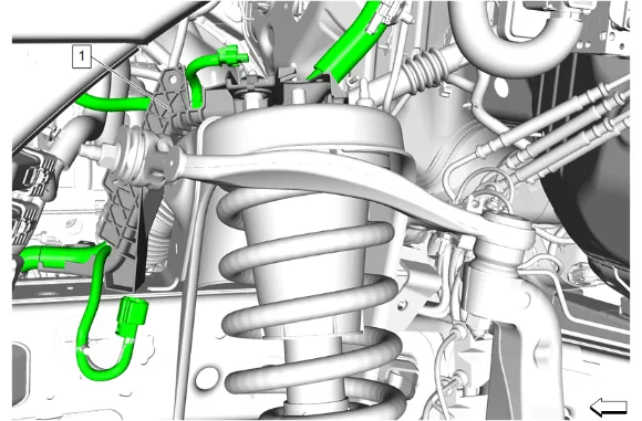
- Unclip and reposition the chassis wiring harness bracket (1) away from the frame shock tower.
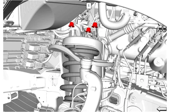
- Front Shock Absorber Nut (1) » Remove [3x]
- Support the front lower control arm with a suitable jack stand.
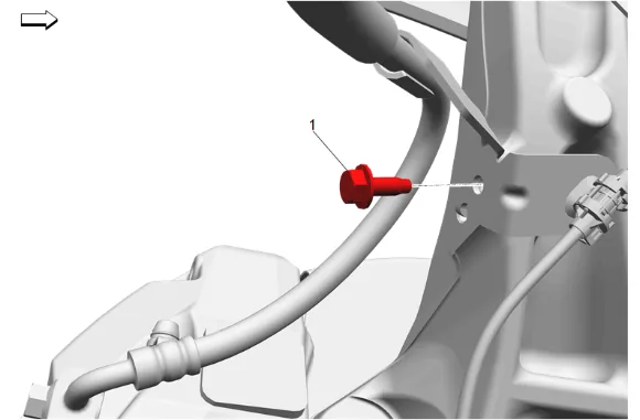
- Front Brake Hose Bracket Bolt (1) » Remove
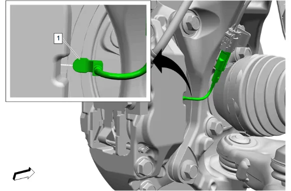
- { If equipped } Front Disc Brake Pad Wear Sensor (1) @ Front Brake Caliper » Remove
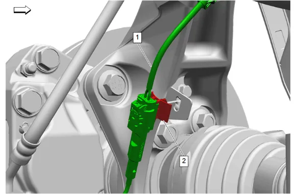
- { If equipped } Front Disc Brake Pad Wear Sensor Retainer (2) » Remove
- { If equipped } Position the front disc brake pad wear sensor wiring harness (1) out of the way.
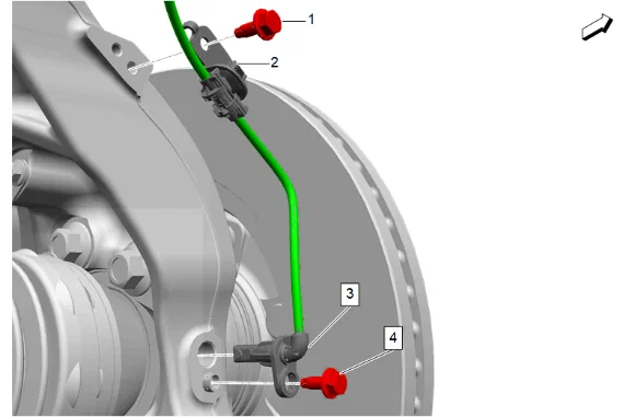
- Front Wheel Speed Sensor Bolt (4) » Remove
- Front Wheel Speed Sensor Bracket Bolt (1) » Remove
- Front Wheel Speed Sensor (3) » Remove
- Front Wheel Speed Sensor Bracket (2) » Remove
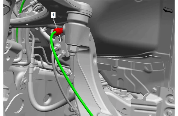
- Front Wheel Speed Sensor Wiring Harness (1) @ Wiring Harness Bracket » Remove
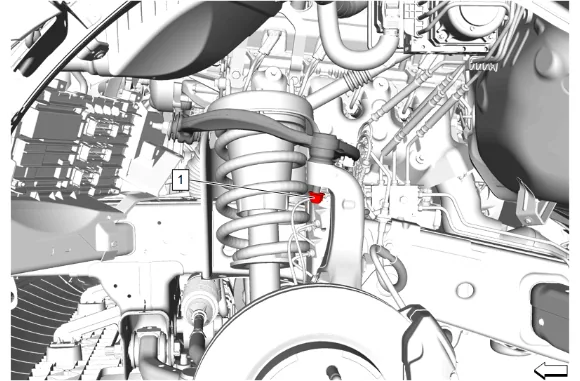
- Front Upper Control Arm Ball Stud Nut (1) » Loosen
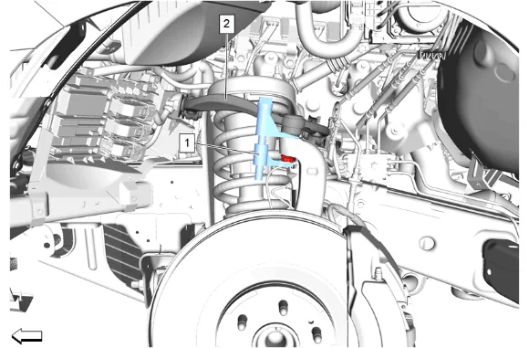
- Using the CH-42188–B Ball Joint Separator(1) , separate the left front upper control arm (2) from the steering knuckle.
- Remove the CH-42188–B Ball Joint Separator(1) from the left front upper control arm (2) and the steering knuckle.
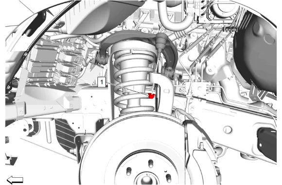
- Front Upper Control Arm Ball Stud Nut (1) » Remove
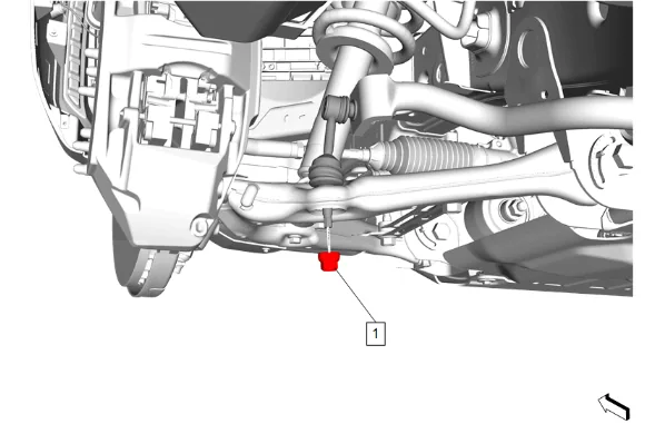
- Front Stabilizer Shaft Link Nut (1) » Remove
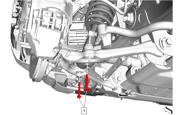
- Front Shock Absorber Bolt (1) » Remove [2x]
- Remove the jack stand from under the front suspension lower control arm.
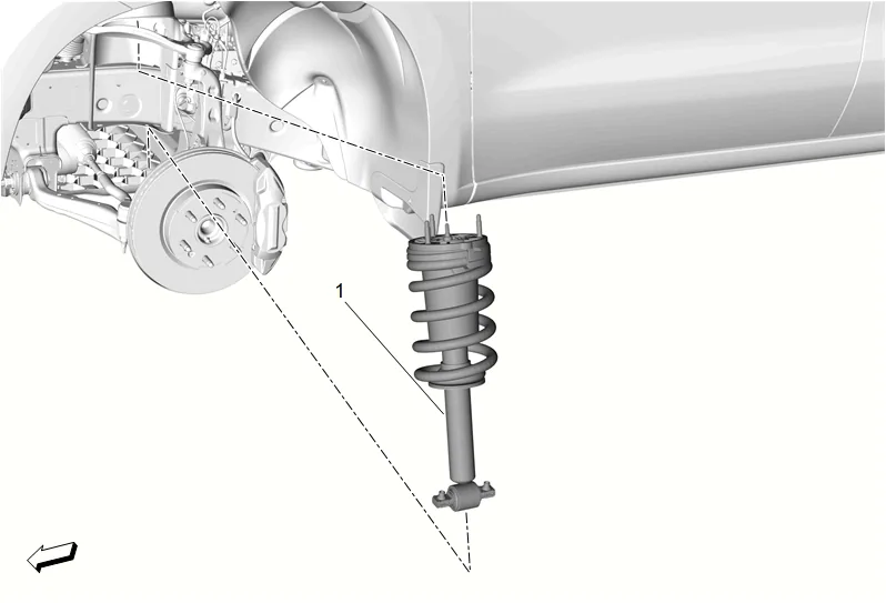
- Front Shock Absorber (1) » Remove Installation Procedure
-
Apply anti-corrosion wax to the frame shock tower. Anti-Corrosion Treatment and Repair
-
Front Shock Absorber (1) » Install
-
Front Shock Absorber Bolt (1) » Install and tighten [2x] — Fastener Specifications
-
Front Stabilizer Shaft Link Nut (1) » Install and tighten — Fastener Specifications
-
Front Upper Control Arm Ball Stud Nut (1) » Install and tighten — Fastener Specifications
-
Front Shock Absorber Nut (1) » Install and tighten [3x] — Fastener Specifications
-
Reposition and install the chassis wiring harness bracket (1) to the frame shock tower.
-
Front Wheel Speed Sensor Wiring Harness (1) @ Wiring Harness Bracket » Install
-
Front Wheel Speed Sensor Bracket (2) » Install
-
Front Wheel Speed Sensor Bracket Bolt (1) » Install and tighten — Fastener Specifications
-
Front Wheel Speed Sensor (3) » Install
-
Front Wheel Speed Sensor Bolt (4) » Install and tighten — Fastener Specifications
-
{ If equipped } Position the front disc brake pad wear sensor wiring harness (1) into place.
-
{ If equipped } Front Disc Brake Pad Wear Sensor Retainer (2) » Install
-
{ If equipped } Front Disc Brake Pad Wear Sensor (1) @ Front Brake Caliper » Install
-
Front Brake Hose Bracket Bolt (1) » Install and tighten — Fastener Specifications
-
Remove the jack stand from under the front lower control arm.
-
Install the tire and wheel assembly. Tire and Wheel Removal and Installation