Transfer Case Description and Operation
The Magna Powertrain (MP) model 3025 RPO NQH transfer case is a 2 speed automatic, active transfer case (ATC). The MP 3025 ATC provides 5 modes, Auto 4WD, 4HI, 4LO, 2HI and NEUTRAL. The Auto 4WD position allows the capability of an active transfer case, which provides the benefits of on-demand torque biasing wet clutch and easy vehicle tuning through software calibrations. The software calibrations allow more features such as flexible adapt ready position and clutch preload torque levels. The technology allows for vehicle speed dependent clutch torque levels to enhance the performance of the system. For example, the system is calibrated to provide 0–6.78 Y (0–5 lb ft) of clutch torque during low speed, low engine torque operation, and predetermined higher torque for 40 km/h (25 mph) and greater. This prevents crow-hop and binding at low speeds and provides higher torque biases at higher vehicle speeds, in order to enhance stability. Transfer Case Shift Control Switch
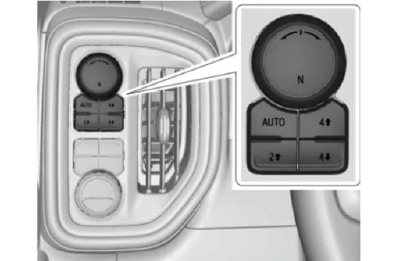
The MP 3025 ATC transfer case features a 5 mode shift control switch located on the instrument panel. When the ignition key is in the RUN position, the transfer case shift control module monitors the transfer case shift control switch to determine if the driver desires a new mode/range position. To command a shift, press button of the new desired state. The actual 4x4 shift request is only made after the button is released. Transfer Case state will be displayed in the Cluster at all times. Graphic location could vary depending on trim level. However, graphics will be consistent. The graphic in the cluster will blink while a shift is in progress. The graphic will change to indicate the mode requested. When the shift is complete, the graphic will stop blinking and become steady. If the transfer case cannot complete a shift, the graphic will return to the previously selected mode. While shift is in progress, cluster will display following DIC message: “4WD Shift in Progress”. The DIC message will turn off once the shift is complete. During normal driving situations, the transfer case can operate in the Auto 4WD mode. In the Auto 4WD mode, the transfer case shift control module monitors rear wheel slip speed, based on the inputs from the wheel speed sensors and/or vehicle speed sensor. When the vehicle experiences a rear wheel slip condition, the transfer case shift control module sends a pulse width modulated (PWM) signal to an electronic motor, which is the transfer case 2/4 wheel drive actuator assembly. This actuator rotates the transfer case control actuator shaft, applying a clutch. The clutch is designed to deliver a variable amount of torque, normally delivered to the rear wheels, and transfers it to the front wheels. Torque is ramped up to the front wheels until the front wheel speed sensor matches that of the rear wheel speed sensors and/or vehicle speed sensor. Torque is ramped down to the front wheels. The process would repeat if rear wheel slip is detected again. The MP 3025 ATC transfer case has the added feature of also providing the driver with 4 manual mode/range positions: 4HI – 4 Wheel Drive high range 2HI – 2 Wheel Drive high range 4LO – 4 wheel drive low range, 2.72:1 gear ratio reduction. Neutral The driver may choose to select any of these mode/range positions while driving the vehicle. However, the transfer case will not allow a shift into or out of 4LO unless the following criteria has been met: The ignition switch is in RUN. The automatic transmission is in NEUTRAL. The vehicle speed is below 5 km/h (3 mph). This transfer case also has a NEUTRAL position. A shift to the NEUTRAL position allows the vehicle to be towed without rotating the transmission output shaft. In the NEUTRAL position, the rear propeller shaft rotates the transfer case rear output shaft, in turn rotating the oil pump, thus providing constant lubrication during towing. NEUTRAL position may be obtained only if the following criteria have been met: Start the vehicle or turn the ignition on. Shift the transmission to NEUTRAL. Shift the transfer case to 2 HI. (Shifts to transfer case neutral are only allowed when transfer case initial state is 2 HI.) Apply park brake and/or Service brake. If Park Brake and/or service brake is not applied within 20 seconds, transfer case will remain in original state. Once these conditions have been met, Press 2 HI 5 sequential times in 10 seconds until the Transfer Case N (Neutral) graphic starts blinking in cluster. When shift to Transfer Case N (Neutral) is complete, graphic in cluster will be steady. When the system completes the shift to NEUTRAL, the red NEUTRAL lamp will illuminate. 2WD Mode Power Flow
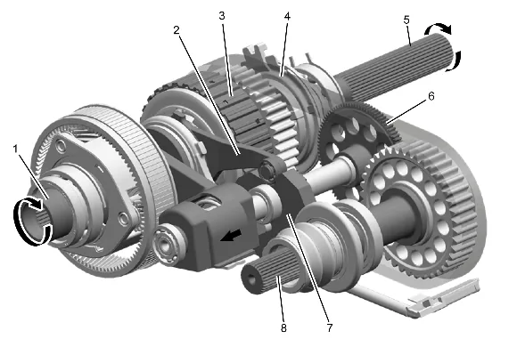
(1) Transfer Case Input Shaft (2) Transfer Case Scissor Mechanism Lever (3) Transfer Case Four Wheel Drive Clutch Pack (4) Transfer Case Front Output Shaft Drive Chain Assembly (5) Transfer Case Rear Output Shaft (6) Transfer Case Two/Four Wheel Drive Actuator Shaft Gear (7) Transfer Case Two/Four Wheel Drive Actuator Cam (8) Transfer Case Front Output Shaft 2WD Mode Power Flow
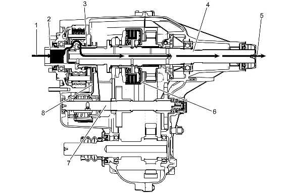
When the MP 3025 ATC is in the 2WD mode, the power flows from the transmission (1) to the input shaft (2). The input shaft (2) is connected to the rear output shaft (4) by the high/low clutch (3). The high/low clutch (3) outer teeth are engaged with the input shaft (2) inner, high-speed position teeth. At the same time the high/low clutch is slip splined to the rear output shaft (4). The rear output shaft (4) delivers the power flow to the rear propshaft (5). The position of the control actuator shaft (7) allows no clutch (6) engagement. The high/low range shift fork (8), is in the high-speed position on the control actuator shaft (7). 4HI Mode Power Flow
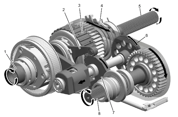
(1) Transfer Case Input Shaft (2) Transfer Case Scissor Mechanism Lever (3) Transfer Case Four Wheel Drive Clutch Pack (4) Transfer Case Front Output Shaft Drive Chain Assembly (5) Transfer Case Rear Output Shaft (6) Transfer Case Two/Four Wheel Drive Actuator Shaft Gear (7) Transfer Case Two/Four Wheel Drive Actuator Cam (8) Transfer Case Front Output Shaft 4HI Mode Power Flow
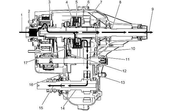
In the 4HI mode, the power flow to the rear propshaft (9) is the same as it is in the 2WD mode. To deliver power flow to the front propshaft (15) during the 4HI position, the transfer case control module commands the 2/4 wheel drive actuator assembly (13) to apply the clutch to a calibrated torque. The 2/4 wheel drive actuator assembly (13) turns the control actuator shaft. A brake in the 2/4 wheel drive actuator assembly (13) holds the control actuator shaft in the full clutch position. The control actuator shaft is cam designed and the cam action moves the control actuator lever (12). The control actuator lever (12) pivots against the control lever (17) and moves toward the clutch pressure plate (4), to engage the clutch (5). As more pressure is applied to the clutch pressure plate (4), the clutch discs (5) are compressed. Using inner clutch discs, which are engaged with the clutch hub, and the outer clutch discs, which are engaged with the clutch housing (6), the power flow is delivered to the clutch housing (6). The clutch hub is splined to the rear output shaft (8), and the clutch housing (6) rotates on a needle bearing on the rear output shaft (8). The chain drive sprocket (7) is splined to the clutch housing (6). The power flows from the drive sprocket (7), through the chain (10), to the chain driven sprocket. The driven sprocket is splined to the front output shaft (14). The power flow is delivered to the front propshaft (15) through the front output shaft (14). During the Auto 4WD mode, the power flow is the same as it is in the 4HI mode. Except, during the Auto 4WD mode, the 2/4 wheel drive actuator assembly (13) rotates the control actuator shaft to the correct torque level positions. Rotating the control actuator shaft to the various positions changes the clutch torque level. When a difference of front wheel speed to rear wheel speed is recognized, the transfer case control module commands for more, or less clutch torque. Auto 4WD Mode Power Flow
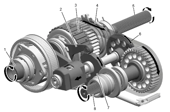
(1) Transfer Case Input Shaft (2) Transfer Case Scissor Mechanism Lever (3) Transfer Case Four Wheel Drive Clutch Pack (4) Transfer Case Front Output Shaft Drive Chain Assembly (5) Transfer Case Rear Output Shaft (6) Transfer Case Two/Four Wheel Drive Actuator Shaft Gear (7) Transfer Case Two/Four Wheel Drive Actuator Cam (8) Transfer Case Front Output Shaft AUTO 4WD Mode Power Flow
During the Auto 4WD mode, the power flow is the same as it is in the 4HI mode. Except, during the Auto 4WD mode, the 2/4 wheel drive actuator assembly (13) rotates the control actuator shaft to the correct torque level positions. Rotating the control actuator shaft to the various positions changes the clutch torque level. When a difference of front wheel speed to rear wheel speed is recognized, the transfer case control module commands for more or less clutch torque. 4LO Mode Power Flow
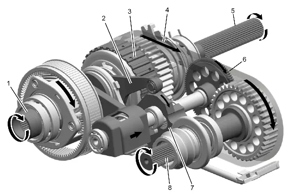
(1) Transfer Case Input Shaft (2) Transfer Case Scissor Mechanism Lever (3) Transfer Case Four Wheel Drive Clutch Pack (4) Transfer Case Front Output Shaft Drive Chain Assembly (5) Transfer Case Rear Output Shaft (6) Transfer Case Two/Four Wheel Drive Actuator Shaft Gear (7) Transfer Case Two/Four Wheel Drive Actuator Cam (8) Transfer Case Front Output Shaft 4LO Mode Power Flow
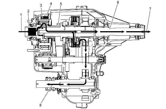
When shifting the transfer case to the 4LO mode, it commands the 2/4 wheel drive actuator assembly to turn the control actuator shaft, to move the high/low shift fork (9). The shift fork (9) moves the high/low clutch (5), which is slip splined on the rear output shaft (6) toward the rear of the transfer case. The high/low clutch (5) outer teeth disengage from the input shaft (2) inner teeth. The high/low clutch (5) outer teeth then engage in the planetary carrier teeth. The power flow is now from the input shaft (2) planetary teeth to the planetary gears (3) in the carrier. Rotating the planetary gears (3), which are engaged in the high/low internal gear (4), the planetary carrier rotates. The planetary carrier engaged to the high/low clutch (5), drives the rear output shaft (6), providing a 2.72 reduction to the speed of the rear output shaft (6). The power flow to the front propshaft (8) is the same as it is in the 4HI. NEUTRAL Mode Power Flow Shifting to the NEUTRAL position, the high/low clutch is centered between the input shaft and the high/low planetary carrier. The high/low clutch is not engaged with either the input shaft or the high/low planetary carrier teeth. Service 4 Wheel Drive Message The Service 4 Wheel Drive Message is a display within the Drivers Information Center (DIC) and cannot be serviced separately. This message is used to inform the driver that a transfer case system malfunction has occurred. The Service 4 Wheel Drive Message is controlled by the transfer case shift control module via GMLAN. Transfer Case Two/Four Wheel Drive Actuator Assembly
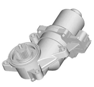
The transfer case two/four wheel drive actuator assembly consists of a permanent magnet DC motor and gear reduction assembly. It is located on the left hand side, driver’s side, of the transfer case. When activated, it rotates the shift detent lever shaft of the transfer case, clockwise or counterclockwise, to shift the transfer case. The motor/encoder is controlled with a PWM signal by the transfer case shift control module. This circuit consists of a driver on both the Motor A and Motor B circuits. The encoder motor is bi-directional in order to allow the motor to shift the transfer case from 2HI or 4HI to NEUTRAL and 4LO positions. The two/four wheel drive incremental sensor and motor lock are internal to the actuator motor assembly. Transfer Case Motor Lock The transfer case motor lock is internal to the transfer case actuator motor and is replaced with the actuator motor as an assembly. The motor lock is used to provide a 2HI, 4HI, and 4LO motor locking feature. When the lock circuit is energized, the transfer case actuator motor is allowed to turn. When the transfer case is placed 2HI, 4HI, or 4LO the motor lock circuit is de-energized and the lock is applied. This assures that the transfer case remains in the current gear position until a new gear position is requested. When AUTO 4WD is selected, the motor lock remains applied until an adaptive mode torque being applied to the front propshaft is required. During an adaptive mode condition the motor lock circuit is energized and the motor lock is released, enabling the actuator motor to turn and apply or release torque at the front propshaft. Transfer Case Two/Four Wheel Drive Incremental Sensor The incremental sensor is internal to the transfer case actuator motor and is replaced with the motor as an assembly. The incremental sensor converts the shift detent lever shaft position, representing a mode or range, into an electrical signal input to the transfer case shift control module. The module detects what position the transfer case is in by monitoring the voltage returned on the incremental encoder impulse signal circuit. This voltage translates into AUTO 4WD, 2HI, 4HI, NEUTRAL, and 4LO or in transition between gears. Transfer Case Actuator Shaft Position Sensor Assembly
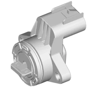
This sensor works in conjunction with the incremental sensor and shows transfer case position in degrees. Transfer Case Shift Control Module
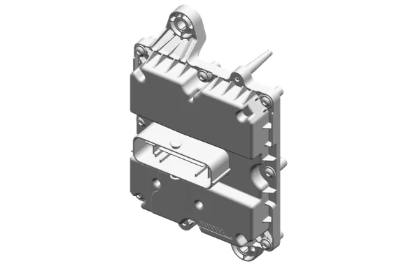
The transfer case shift control module uses the vehicle identification number (VIN) information for calculations based on axle ratio, transmission, tire size, and engine size. For StabiliTtrak applications, when the vehicle is in the AUTO 4WD mode, the transfer case shift control module monitors the wheel speed via the four wheel speed sensors in order to detect wheel slippage. For non-StabiliTrak applications, when the vehicle is in the AUTO 4WD mode, the transfer case shift control module monitors the wheel speed via the two front wheel speed sensors and the vehicle speed sensor in order to detect wheel slippage. When wheel slippage is detected, the module applies a clutch pack contained inside the transfer case. This clutch pack is used to lock-in and apply the front propshaft, transferring torque to the front wheels. The clutch pack is applied by a motor/encoder assembly. When slip is no longer detected by the transfer case shift control module, the clutch is no longer applied.